


Introduction
In the realm of software engineering, one of the most persistent challenges is the disconnect between business stakeholders and technical development teams. Business analysts and process architects typically model organizational workflows using Business Process Model and Notation (BPMN), focusing on operational efficiency and strategic goals. Conversely, software developers rely on Unified Modeling Language (UML) diagrams, such as Use Case diagrams, to define system behaviors and technical requirements. When these two worlds operate in silos, it often leads to misaligned expectations, scope creep, and software that fails to address core business needs.
 into Actionable Software Requirements (Use Cases) Using Visual Paradigm")
Visual Paradigm emerges as a powerful solution to this problem, offering a unified modeling environment that natively bridges the gap between high-level business processes and detailed software design. This case study explores how Visual Paradigm’s advanced toolset facilitates the seamless transition from BPMN workflows to UML Use Cases, ensuring that every line of code traces back to a tangible business objective.
Case Study: Streamlining Requirements Gathering with Visual Paradigm
The Challenge: Aligning Business Operations with System Functions
Organizations undergoing digital transformation often possess complex, well-documented business processes. However, translating these operational workflows into actionable software requirements is a manual, error-prone endeavor. Traditional methods require teams to redraw processes in different formats, losing critical context and traceability along the way. The core challenge is to identify the right requirements (use cases) and stakeholders (actors) directly from existing business process diagrams without duplicating effort or breaking the chain of traceability.
The Platform Capabilities: A Unified Modeling Environment
Visual Paradigm functions as an advanced requirements-gathering environment that extends far beyond simple drag-and-drop vector drawing. The platform provides comprehensive support for both UML and BPMN standards:
-
Comprehensive BPMN 2.0 Compliance: The platform includes a dedicated toolset optimized for process architects, supporting core notation schemas such as Pools, Lanes, Tasks, Sub-processes, and Gateways. It allows for process simulation to locate bottlenecks and optimize enterprise pathways.
-
Advanced UML Use Case Support: Visual Paradigm supports all standard UML use case shapes and includes a built-in Flow of Events Editor to detail scenarios step-by-step. It also features AI generation and refinement tools to rapidly structure use cases based on domain descriptions.
The Solution: The Model Transitor Engine
A key engineering strength of Visual Paradigm is its Model Transitor Engine. This feature enables the direct transition from a BPMN task or sub-process straight into a UML Use Case. By automating the generation of system requirements natively from enterprise workflows, the platform leaves interactive traceability flags on elements. This allows users to trace exactly why a specific software function exists back to its original business lane anchor.
Step-by-Step Implementation: From Fire Safety Processes to Use Cases
To demonstrate this capability in action, we examine a practical implementation using a Fire Safety Department business process model. The objective is to extract software requirements directly from an operational workflow.
Step 1: Project Initialization
The process begins by opening an existing business process project, such as the Fire Safety Department model, within the Visual Paradigm environment.
Step 2: Identifying Business Goals as Use Cases
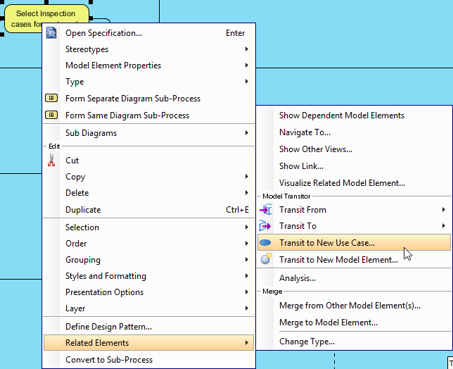
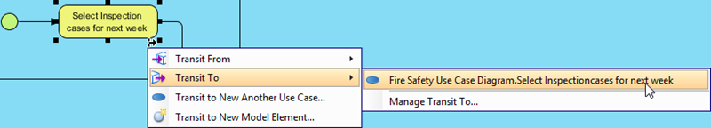
By reviewing the business process diagram, teams can identify tasks or sub-processes that are substantial enough to represent distinct business goals. In this scenario, the task named Select Inspection cases for next week inside the Regular Inspection To-be Process is identified as a prime candidate for a use case. Right-clicking on this task and selecting the option to transit to a new use case initiates the transformation.
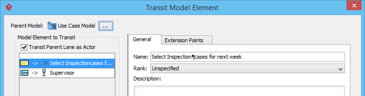
Step 3: Defining the Parent Model
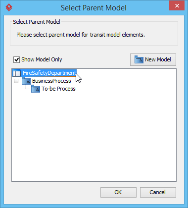
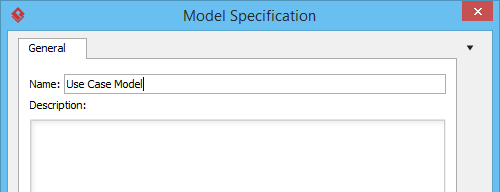
The system prompts the user to specify the storage location for the newly generated use case. By navigating to the project root, a new dedicated model—named Use Case Model—is created to house the software requirements.
Step 4: Automating Actor Identification
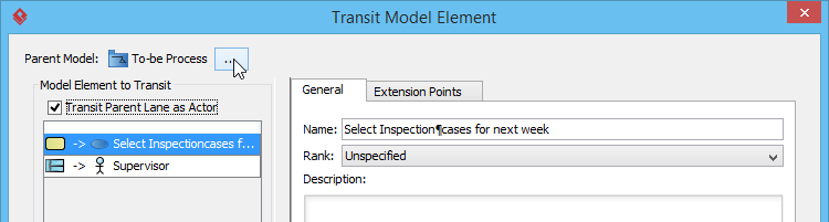
A critical feature of this transition is the ability to automatically identify system actors. By keeping the Transit Parent Lane as Actor option selected, the system automatically creates an actor based on the specific BPMN lane that contained the original task, linking it directly to the newly generated use case.
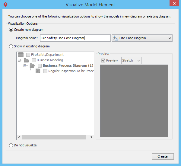
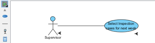
Step 5: Visualizing the Generated Requirements
Once the model elements are configured, the user is prompted to visualize the results. The system generates a comprehensive UML Use Case Diagram, instantly providing the development team with a clear, standardized view of the software requirements.
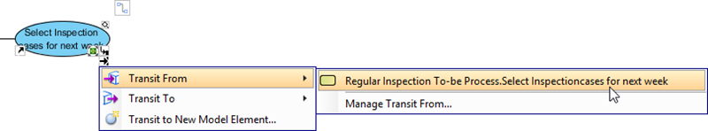
Step 6: Maintaining Continuous Traceability
The true value of this workflow is realized in the ongoing maintenance of the system. Visual Paradigm automatically embeds transit resource icons at the bottom right of the shapes. These interactive links allow business analysts and developers to seamlessly navigate back and forth between the high-level business process and the granular software use case.
Results and Benefits
By leveraging Visual Paradigm’s Model Transitor Engine, organizations achieve several critical outcomes:
-
Elimination of Redundancy: Requirements are not manually re-entered; they are extracted directly from validated business processes.
-
Guaranteed Traceability: Every software feature can be traced back to a specific business need, ensuring alignment with strategic goals.
-
Enhanced Collaboration: Business analysts and development teams work within a shared, synchronized environment, reducing miscommunication and accelerating the software delivery lifecycle.
Conclusion
The transition from business strategy to software execution does not have to be a fragmented journey. As demonstrated through the Fire Safety Department case study, Visual Paradigm provides a robust, integrated framework that unifies BPMN and UML modeling. By automating the extraction of use cases from business process diagrams and maintaining strict traceability, the platform empowers organizations to build software that is not only technically sound but also deeply rooted in real-world business value. In an era where agility and alignment are paramount, tools that bridge the gap between operational workflows and technical design are indispensable for successful digital transformation.
References
- From Business Process to Use Cases: Tutorial on transitioning from BPMN business processes to UML use cases.
- BPMN Diagram and Tools: Detailed features of the BPMN 2.0 diagramming toolset.
- Effortless Project Management with Visual Paradigm: Guide on utilizing Visual Paradigm for streamlined project management.
- Exploring Visual Paradigm Online Diagramming Tool: A comprehensive blog guide to system modeling diagrams.
- UML Use Case Diagram User Guide: Official user guide documentation for creating UML Use Case diagrams.
- Use Case Tool Solution: Overview of the dedicated Use Case modeling solution.
- Use Case Diagram Tutorial: Step-by-step blog tutorial on drawing use case diagrams.
- How to Identify Business Goals of an IT System: Tutorial on extracting IT system goals from business contexts.
- Visual Paradigm User Guide: General user guide documentation for the Visual Paradigm platform.
- Drawing Use Case Diagrams: Specific documentation on the mechanics of drawing use cases.
- Use Case Description Features: Features detailing how to write comprehensive use case descriptions.
- AI Use Case Diagram Refinement Tool: Information on AI-powered tools for refining use case layouts.
- AI Use Case Generation Video: Video demonstration of AI use case generation capabilities.
- AI Use Case Refinement Video: Video tutorial on using AI to refine use case models.
- Testing Visual Paradigm’s AI-Powered BPMN Diagram Generator: Third-party review of the AI BPMN generator for process mapping.
- Business Process User Guide: Documentation for business process modeling tools.
- BPMN Video Tutorial: Video guide on creating BPMN diagrams.
- Drawing BPMN Choreography Diagrams: Guide on mapping multi-party message exchanges using BPMN.
- Identify Use Case by BPD Tutorial: Specific tutorial on identifying use cases from Business Process Diagrams.
