


Introduction
In the modern enterprise, clarity is currency. Whether you are a business analyst drafting initial workflows, a developer implementing automation, or a manager monitoring operational efficiency, everyone needs to speak the same language. This is where Business Process Model and Notation (BPMN) steps in.
Having worked with various modeling standards over the years, I’ve found that BPMN stands out not just for its technical precision, but for its accessibility. It bridges the notorious gap between high-level business strategy and low-level technical execution. This guide is designed to walk you through the essentials of BPMN, breaking down its evolution, core elements, and practical application levels. Whether you are new to process modeling or looking to refine your diagrams, this review-style guide will help you understand how to create processes that are both simple to read and robust enough to handle complex organizational realities.
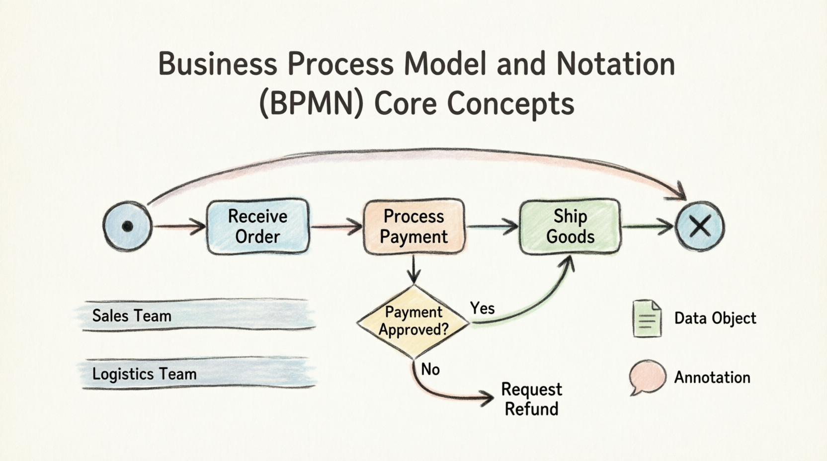
What is BPMN and Why Does It Matter?
At its heart, a business goal is a target an organization aims to achieve by performing related business processes correctly. A business process consists of a set of activities performed in coordination within an organizational and technical environment. These activities jointly realize that business goal.
The primary purpose of BPMN is to provide a notation that is readily understandable by all business users. It serves as a standardized bridge, allowing for the generation of executable code (such as BPEL4WS) from visual models. This means BPMN can be applied at three distinct levels:
-
Descriptive Process Models: Suitable for high-level modeling. These should feel comfortable for analysts familiar with basic flowcharts.
-
Analytic Process Models: These contain the concepts most commonly used and covered in standard BPMN training, allowing for deeper process analysis.
-
Common Executable Process Models: These focus on the specific elements required to create processes that can be directly executed by workflow engines.
The Evolution of the Standard
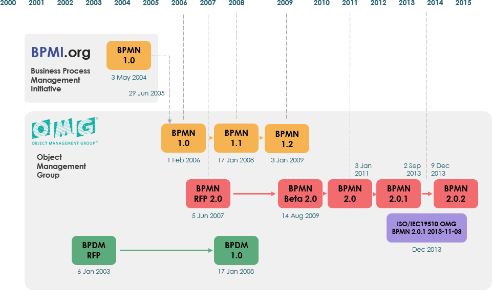
Understanding where BPMN came from helps appreciate its current robustness.
-
Origins: BPMN was originally developed by the Business Process Management Initiative (BPMI).
-
BPMN 1.0: Released to the public in May 2004 after more than two years of effort by the BPMI Notation Working Group.
-
OMG Adoption: The Object Management Group (OMG) released a specification document in February 2006.
-
BPMN 2.0: Developed in 2010, with the actual specification released in December 2013.
-
ISO Standardization: The latest version (2.0.2) was formally published by ISO as the 2013 edition standard: ISO/IEC 19510.
The Core Philosophy: Simplicity Meets Complexity
One of the drivers for BPMN’s development was to create a simple mechanism for creating business process models while simultaneously handling the inherent complexity of real-world business operations.
How did they solve this conflict? By organizing graphical aspects into specific categories. This provides a small set of notation categories so that readers can easily recognize basic element types. Within these basic categories, additional variations and markers can be added to support complexity without dramatically changing the basic “look-and-feel” of the diagram.
The four basic categories of elements are:
-
Flow Objects
-
Connecting Objects
-
Swimlanes
-
Artifacts
1. Flow Objects: The Heart of the Diagram
A Business Process Diagram (BPD) relies on a small set of core elements known as Flow Objects. This ensures modelers don’t have to memorize hundreds of different shapes. There are three primary Flow Objects:
Event
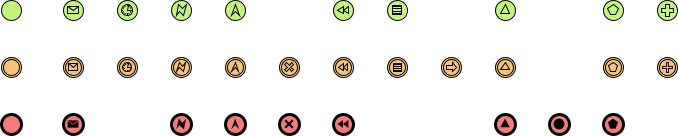
An Event is represented by a circle. It signifies something that “happens” during the course of a business process. Events affect the flow and usually have a cause (trigger) or an impact (result). They have open centers to allow internal markers to differentiate triggers or results.
There are three types of Events based on when they affect the flow:
-
Start Event: Triggers the process.
-
Intermediate Event: Occurs between the start and end.
-
End Event: Marks the conclusion of the process.
Activity
An Activity is represented by a rounded-corner rectangle. It is a generic term for work that the company performs. Activities can be:
-
Task: An atomic activity (one step).
-
Sub-Process: A nonatomic (compound) activity. This is distinguished by a small plus sign (
+) in the bottom center of the shape.
Gateway
A Gateway is represented by a diamond shape. It controls the divergence and convergence of Sequence Flow. Gateways determine decisions, as well as the forking, merging, and joining of paths. Internal markers indicate the type of behavior control.
| Gateway Type | Description | Visual Example |
|---|---|---|
| Exclusive Gateway | Follow only one path (XOR). | 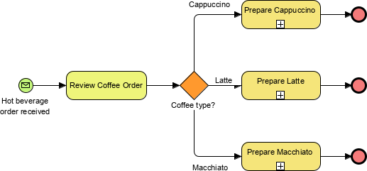 |
| Inclusive Gateway | Follow one or more paths (OR). | 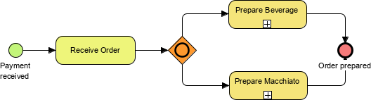 |
| Parallel Gateway | Follow all paths simultaneously (AND). | 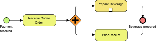 |
Flow Object Summary Visuals
To help visualize these core components, refer to the comprehensive charts below:
Events Overview
Activities Overview

Gateways Overview

2. Connecting Objects: Building the Skeleton
Flow objects are connected to create the skeletal structure of a business process. There are three main Connecting Objects:
Sequence Flow
Represented by a solid line with a solid arrowhead. It shows the order (sequence) in which activities are performed. Note that BPMN generally avoids the term “control flow” in favor of Sequence Flow.
Message Flow
Represented by a dashed line with an open arrowhead. It symbolizes information flow across organizational boundaries (e.g., between two different companies or departments). Message flows can be attached to pools, activities, or message events and can be decorated with an envelope to depict content.
Association
Represented by a dotted line. Associations link Artifacts (like text annotations or data objects) to Flow Objects. They allow additional information relevant to documenting the process to be shown on the diagram.

3. Swimlanes: Organizing Responsibility
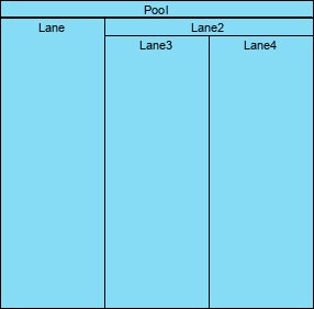
Many process modeling methodologies use swimlanes to organize activities into separate visual categories, illustrating different functional capabilities or responsibilities. BPMN supports this with two main constructs:
Pool
A Pool represents a Participant in a Process. It acts as a graphical container for partitioning a set of activities from other Pools. This is particularly useful in B2B (Business-to-Business) situations where you need to show interactions between different organizations.
Lane
A Lane is a sub-partition within a Pool. It extends the entire length of the Pool, either vertically or horizontally. Lanes are used to organize and categorize activities within a single participant (e.g., separating “Sales Dept” from “Marketing Dept” within the same company pool).
4. Artifacts: Adding Context
BPMN allows modelers flexibility to extend the basic notation to provide context appropriate to specific situations (such as insurance or banking verticals). While any number of artifacts can be added, the specification pre-defines three main types:
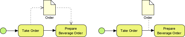
Data Object
Data Objects show how data is required or produced by activities. They are connected to activities through Associations. They do not affect the flow but provide critical context about information usage.
Data Store
A Data Store represents a place where the process can read or write data that persists beyond the scope of the process (e.g., a database or file system).
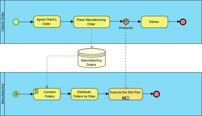
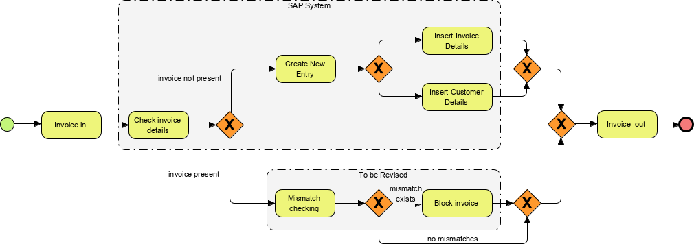
Group
A Group is represented by a rounded-corner rectangle drawn with a dashed line. Grouping is used for documentation or analysis purposes (such as highlighting a specific phase of a project) but does not affect the Sequence Flow.
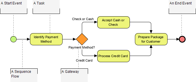
Annotation
Annotations are a mechanism for modelers to provide additional text information for the reader. They are linked via Associations and are essential for explaining complex logic or providing notes.
Handling Complexity: Events in Detail
As mentioned earlier, BPMN handles complexity by adding variations to basic elements rather than creating new shapes. Nowhere is this more evident than in Events.
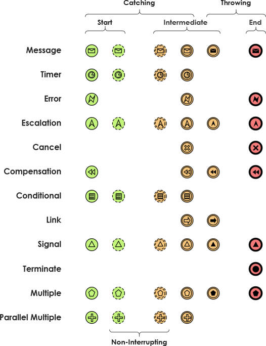
The table below illustrates the complete combination of how events are represented using basic elements plus internal markers. This allows BPMN to support complex scenarios (like timers, errors, or messages) without changing the fundamental look and feel of the notation.
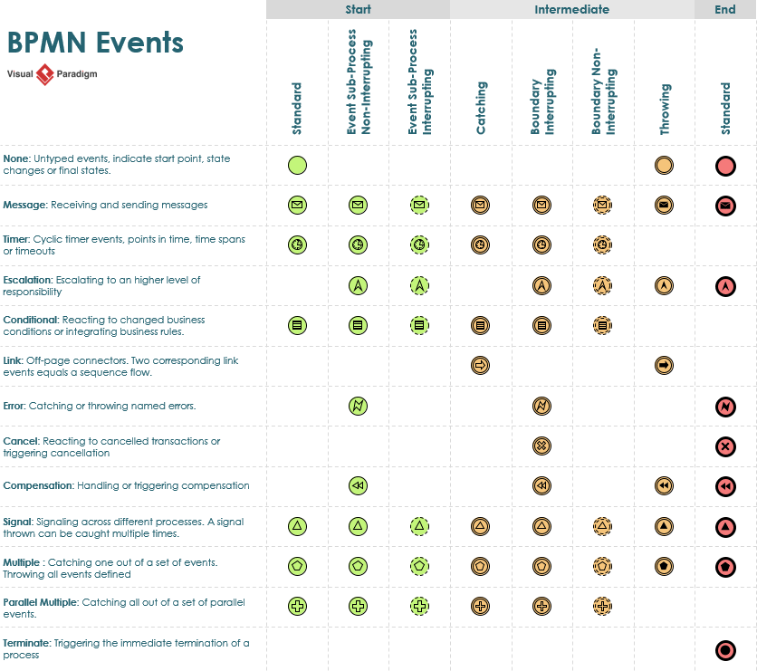
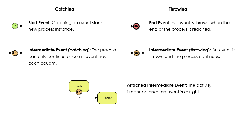
For those diving deeper into event mechanics, understanding the difference between catching (waiting for an event) and throwing (triggering an event) is crucial, as is distinguishing between interrupting and non-interrupting behaviors.
Conclusion
BPMN 2.0 has matured into a powerful standard that successfully balances readability with technical depth. By sticking to a core set of Flow Objects, Connecting Objects, Swimlanes, and Artifacts, it ensures that diagrams remain accessible to business stakeholders while providing enough detail for technical implementation.
Whether you are creating a simple descriptive flowchart for a team meeting or designing an analytic model for process optimization, BPMN provides the toolkit you need. The key to mastery lies in starting simple—using the basic shapes—and gradually incorporating the richer markers and artifacts as your process requirements grow in complexity. With the ISO standardization behind it, BPMN remains the lingua franca of business process management, ensuring that your processes are not just documented, but understood and executable.
Reference
- Visual Paradigm Features: BPMN Diagram and Tools: Overview of core BPMN diagramming features, AI generator, and collaboration tools.
- Business Process Modeling Solution: Details on smart connection rules, process drill-down, and team co-editing capabilities.
- From Narrative to Diagram: How Visual Paradigm’s AI BPMN Generator Transforms Process Modeling Workflows: Explanation of the AI-powered feature that converts plain-English text into BPMN diagrams.
- BPMN Made Easy: Guide on simplifying BPMN modeling and matrix transformation features.
- BPMN Tutorial 1: Comprehensive tutorial covering full BPMN 2.0 notations including events, tasks, and gateways.
- BPMN Tutorial 1 (PDF Format): PDF version of the comprehensive BPMN notation tutorial.
- BPMN Activity Types Explained: Detailed explanation of specialized task types such as Service, User, Manual, and Script tasks.
- Visual Paradigm BPMN Tutorial Video: Video demonstration of resource-centric modeling, swimlane editing, and process drill-down features.
- Unlock the Power of SysML Modeling with Visual Paradigm: Guide discussing resource-centric modeling principles applicable to BPMN.
- BPMN Swimlane Tutorial: Tutorial focused on flexible swimlane editing and partitioning processes.
- Visual Paradigm Features: BPMN Diagram and Tools: Additional details on process drill-down and nesting complex diagrams.
- Visual Paradigm: The Ultimate All-in-One Software for Software Development: Blog post highlighting the all-in-one nature of the tool, including BPMN capabilities.
- Business Process Modeling Guide: Guide covering process simulation, animation, and gap analysis tools.
- Visual Paradigm Features: BPMN Diagram and Tools: Information on matrix transformation features for RACI and CRUD matrices.
- BIMP BPMN Simulator: External reference related to BPMN simulation concepts.
- Compare Database Schemas Visually: Tutorial on visual comparison techniques, relevant to version diff features.
- Unleash the Power of Visual Paradigm: Your Ultimate REST API Design and Documentation Solution: Guide discussing integration capabilities, including agile backlog synchronization.
- Introduction of Visual Paradigm: Visual Paradigm Editions: PDF document detailing the differences between Community, Professional, and Enterprise editions.
Related posts:
 Visual Paradigm Online PowerPoint Web Viewer: Convert PPT to HTML5 with Animations & Transitions
 Visual Paradigm: All-in-One Diagramming & Project Management Tool – UML, SysML, BPMN, ERD, UX & More
 Complete Guide to Visual Paradigm Online Office Suite
 VPasCode Feature Review Guide: The Ultimate Diagram-as-Code Solution for Modern Teams

 English
 Arabic
 Chinese (Simplified)
 Dutch
Dutch French
 German
 Italian
 Japanese
 Korean
 Portuguese
 Russian
 Spanish