


Choosing between BPMN (Business Process Model and Notation) and UML (Unified Modeling Language) is one of the most common dilemmas for teams involved in process improvement and software development. Both are powerful, standardized modeling languages, but they serve fundamentally different purposes. This comprehensive guide will walk you through their key differences with practical examples and show you how to leverage Visual Paradigm’s integrated tooling to get the best of both worlds.
The Core Difference: Business vs. Software
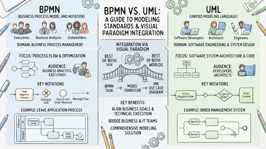
The most critical distinction is their primary domain of application. BPMN is a standardized graphical notation specifically designed for drawing business processes in a workflow, while UML is a general-purpose, developmental modeling language in the field of software engineering.
In practice, this translates to their audience and purpose:
-
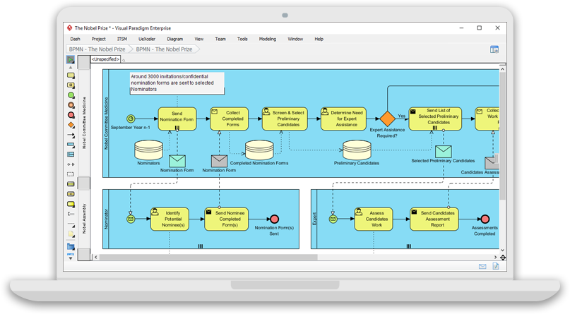
BPMN is for business analysts, executives, and stakeholders who need to visualize, analyze, and optimize business operations. Its visual language is designed to be intuitive for non-technical audiences.
-
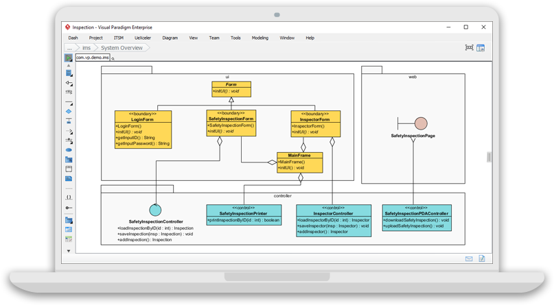
UML is for software developers, architects, and engineers who need to model software systems, components, and interactions. Its diagrams are more technical and detailed, requiring a higher level of technical knowledge to interpret.
Level of Abstraction: High-Level Flow vs. Detailed Design
A fundamental difference lies in their level of abstraction.
-
BPMN operates at a higher level of abstraction, focusing on the flow and interactions of business processes. It provides less detailed information about software implementation and more about the business-level processes and their participants.
-
UML covers a range of abstraction levels, from high-level system architecture to low-level implementation details like classes, objects, and deployment configurations.
Key Concepts and Examples
To better understand their differences, let’s explore the core concepts of each language.
BPMN Key Concepts & Examples
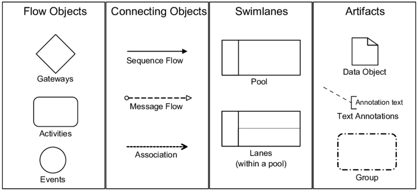
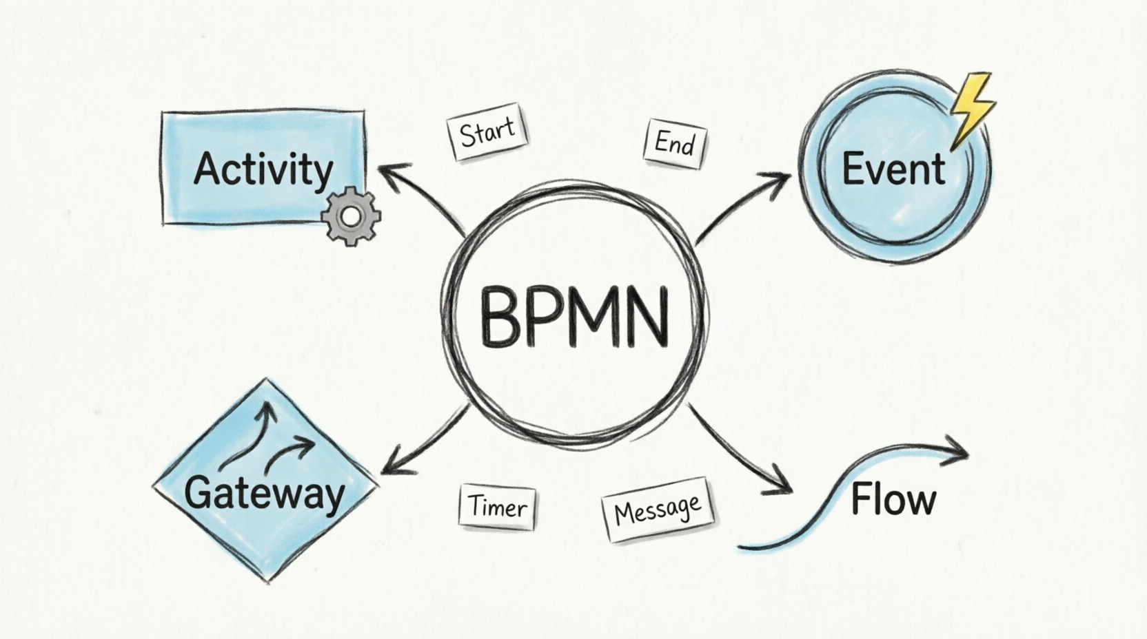
BPMN uses a flowchart-based notation, making it accessible to all business users. The main building blocks are:
-
Flow Objects: The primary elements defining the process behavior.
-
Events: Represent something that “happens” during the process. They are circles.
-
Start Event: Marks the beginning of a process. (e.g., “Order Received”).
-
End Event: Marks the end of a process.
-
Intermediate Event: Occurs between the start and end. (e.g., a timer waiting for 60 minutes).
-
-
Activities: Represent work performed, shown as rounded rectangles.
-
Task: A single unit of work (e.g., “Approve Invoice”).
-
Sub-Process: A process within a process (e.g., “Perform Credit Check”), which can be “opened up” to reveal a lower-level process flow using Visual Paradigm’s Process Drill-Down feature.
-
-
Gateways: Control how sequence flows converge and diverge within a process, shown as diamonds.
-
XOR Gateway: Represents a decision, where only one path is chosen.
-
AND Gateway: Represents parallel processing, where all paths are taken simultaneously.
-
-
-
Connecting Objects: Link the Flow Objects to define the sequence and communication.
-
Sequence Flow: A solid line with an arrow showing the order of activities.
-
Message Flow: A dashed line showing communication between different participants (pools).
-
-
Swimlanes: Used to organize and categorize activities by participant or role.
-
Pool: Represents a major participant, like a company or department. A pool can be shown as a “black box” where internal details are hidden, representing a role solely.
-
Lane: A sub-division of a pool for specific roles or departments (e.g., “Sales Team,” “Finance Team”). Lanes can even be nested to create a more granular structure.
-
BPMN Example: Leave Application Process
A classic example is a leave application process within a company.
-
Participants (Pools): Employee and Manager.
-
Lanes: Within the “Manager” pool, you could have lanes for “Human Resources” and “Department Head” to show specific review steps.
-
Flow:
-
Start Event: “Employee submits leave request.”
-
Task: “Manager reviews request.”
-
Gateway (XOR): “Is request approved?”
-
Approved Path: Task -> “Update leave balance” -> End Event.
-
Rejected Path: Task -> “Notify employee” -> End Event.
-
-
This diagram visualizes the entire process, making it easy for all stakeholders to understand the workflow and responsibilities.
UML Key Concepts & Examples
UML is a more extensive toolkit with multiple diagram types. For business process modeling, the most relevant is the Activity Diagram.
UML Activity Diagram for Business Processes
An Activity Diagram in UML shares similarities with BPMN as it also models workflows. However, it’s framed within the software engineering context. Key elements include:
-
Initial Node: The starting point.
-
Activity Final Node: The ending point.
-
Actions: Represent steps in the workflow.
-
Control Flows: Arrows showing the flow of control.
-
Decision Nodes: Represent branching (like BPMN gateways).
-
Partitions (Swimlanes): Group actions by the object responsible.
UML Example: Order Management System
Consider the order management process for a software system. While a BPMN diagram might show the entire business process from “Customer sends an order” to “Dispatch the order,” a UML Activity Diagram for the same process would be used to define the software’s internal logic.
The activity diagram would detail:
-
Action: “Customer sends an order request.”
-
Decision Node: “Is the order a special order?”
-
Special Order Path: A series of actions to handle special orders.
-
Normal Order Path: A series of actions for normal orders.
-
-
Action: “Confirm the order.”
-
Action: “Dispatch the order.”
The Relationship Between BPMN and UML Diagrams
BPMN and UML can be complementary. For example, BPMN tasks can often be used as a starting point to identify the use cases of a system, as they represent the day-to-day activities of stakeholders. In Visual Paradigm, you can use the Model Transitor feature to create use case diagrams directly from BPMN tasks and sub-processes, effectively bridging the gap between business process modeling and software requirements analysis.
The Business Process Diagram provides the “what” (the business goal), while the UML Use Case Diagram starts to define the “how” (the system’s interactions with actors) to achieve that goal.
Which is Right for Your Needs? (BPMN vs. UML)
The choice depends on your specific goals, the nature of the project, and your audience.
| Feature | BPMN | UML |
|---|---|---|
| Primary Domain | Business Process Management, Workflow Design, Process Optimization. | Software Engineering, System Design, Object-Oriented Analysis and Design. |
| Target Audience | Business Analysts, Executives, Stakeholders, Process Owners. | Software Developers, System Architects, Engineers. |
| Level of Abstraction | High-level, focuses on business flow and participants. | Varies from high-level architecture to low-level implementation. |
| Key Strength | Intuitive and easily understandable for non-technical users. | Comprehensive and detailed for software design and documentation. |
| Examples | Business process improvement, workflow automation, compliance documentation. | Software architecture modeling, class structure design, sequence diagrams for code generation. |
The Hybrid Approach
In many modern projects, the best approach is a hybrid one. A project may require end-to-end modeling where different aspects are covered by BPMN and UML diagrams respectively.
-
You can use BPMN to model the overall business process, manage design and engineering teams, and align the project with business goals.
-
You can use UML for the detailed software design, defining the system architecture, classes, and interactions needed to support the business process.
Why Visual Paradigm is the Ideal Tool for Both
Visual Paradigm is more than just a BPMN modeling tool; it’s a comprehensive solution that empowers you to analyze, improve, and optimize your business processes. It stands out because it’s an all-rounded visual modeling tool that supports a wide range of diagrams, including BPMN and all 14 UML diagrams.
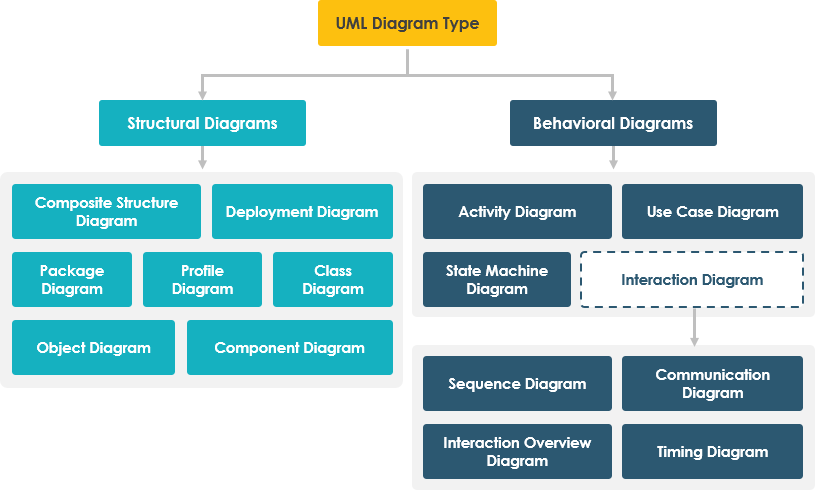
This is the key: Visual Paradigm integrates these models to maximize the effectiveness of visual modeling. You can map a process flow with other modeling artifacts like UML shapes, ERD entities, and wireframes, providing unprecedented flexibility.
Key Visual Paradigm Features for BPMN and UML:
-
Intuitive BPMN 2.0 Modeler: Easily create professional Business Process Diagrams with a user-friendly interface.
-
Process Drill-Down: “Open up” a sub-process to model the lower-level flow in another diagram, providing a comprehensive view of your workflows.
-
Model Transitor: Create UML diagrams like Use Case Diagrams directly from BPMN tasks and sub-processes, seamlessly connecting business and technical modeling.
-
Process Animation: Bring your business process designs to life by converting static diagrams into dynamic, animated models to illustrate the flow.
-
Process Simulation: Visually simulate process execution to study resource consumption, evaluate costs, and identify bottlenecks.
-
As-is and To-be Process Modeling: Produce a target process model (To-be) from a baseline (As-is) and start editing to represent the expected result of process improvement, with traceability maintained between the two models.
-
RACI and CRUD Charts: Create responsibility assignment matrices (RACI) or custom charts to clarify roles and responsibilities within your business processes.
Conclusion
Choosing between BPMN and UML is not about which is “better,” but about which is the right tool for the right job. BPMN is your go-to for business process clarity, communication, and optimization. UML is your solution for detailed software design and system architecture. However, for complex projects, you don’t have to choose one over the other. Using a tool like Visual Paradigm, which integrates both languages, allows you to use BPMN and UML together, creating a complete model that bridges the gap between business goals and technical execution. This hybrid approach ensures that your software is not only technically sound but also perfectly aligned with the business processes it is designed to support.
References
- Visual Paradigm Features: Visual Paradigm provides a fully comprehensive, standards-compliant BPMN 2.0 modeling platform tailored for business analysts and developers alike, blending traditional diagramming with advanced automation and simulation.
- BP Modeling Solution: Offers smart connection rules, flexible swimlane editing, and resource-centric modeling to optimize operational workflows and prevent invalid sequence paths.
- AI BPMN Generator Guide: Explains how the AI BPMN Diagram Generator automatically translates plain-English process narratives into fully interactive, standard-compliant BPMN 2.0 layouts.
- BPMN Made Easy: Highlights tools for simplifying BPMN modeling, including process animation and gap analysis for non-technical stakeholders.
- BPMN Tutorial 1: Provides foundational tutorials on BPMN notations, including events, specialized task types, gateways, and data objects.
- BPMN Tutorial PDF: A downloadable PDF version of the foundational BPMN tutorial for offline reference.
- BPMN Activity Types Explained: Detailed guide on different BPMN activity types, helping users choose between Service, User, Manual, and Script tasks.
- Visual Paradigm YouTube Demo: Video demonstration of Visual Paradigm’s features, including swimlane editing and process drill-down capabilities.
- SysML Modeling Guide: Discusses resource-centric modeling where elements are created as reusable model components rather than static shapes.
- BPMN Swimlanes Tutorial: Focuses on partitioning processes using interactive horizontal or vertical pools and lanes.
- BPMN Diagram Tools Overview: Reiterates the comprehensive feature set for BPMN diagramming, including full notation support and AI integration.
- Visual Paradigm Blog: Discusses Visual Paradigm as an all-in-one software solution, emphasizing its role in software development and process modeling.
- Business Process Modeling Guide: Covers best practices for business process modeling, including As-Is and To-Be gap analysis.
- BPMN Features List: Lists key features such as process simulation, animation, and matrix transformation for RACI/CRUD outputs.



 English
 Arabic
 Chinese (Simplified)
 Dutch
Dutch French
 German
 Italian
 Japanese
 Korean
 Portuguese
 Russian
 Spanish