


A UML sequence diagram shows how participants interact over time. Participants are arranged horizontally, messages flow between them, and time progresses from top to bottom. The diagram emphasizes which participant sends each message, who receives it, and in what order. Vertical spacing indicates ordering—not elapsed duration.
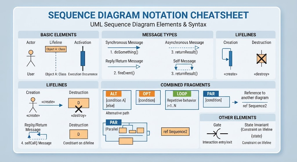
This guide explains the concepts represented in the cheatsheet and shows equivalent PlantUML examples, followed by a Visual Paradigm workflow.
1. Core notation
Actor
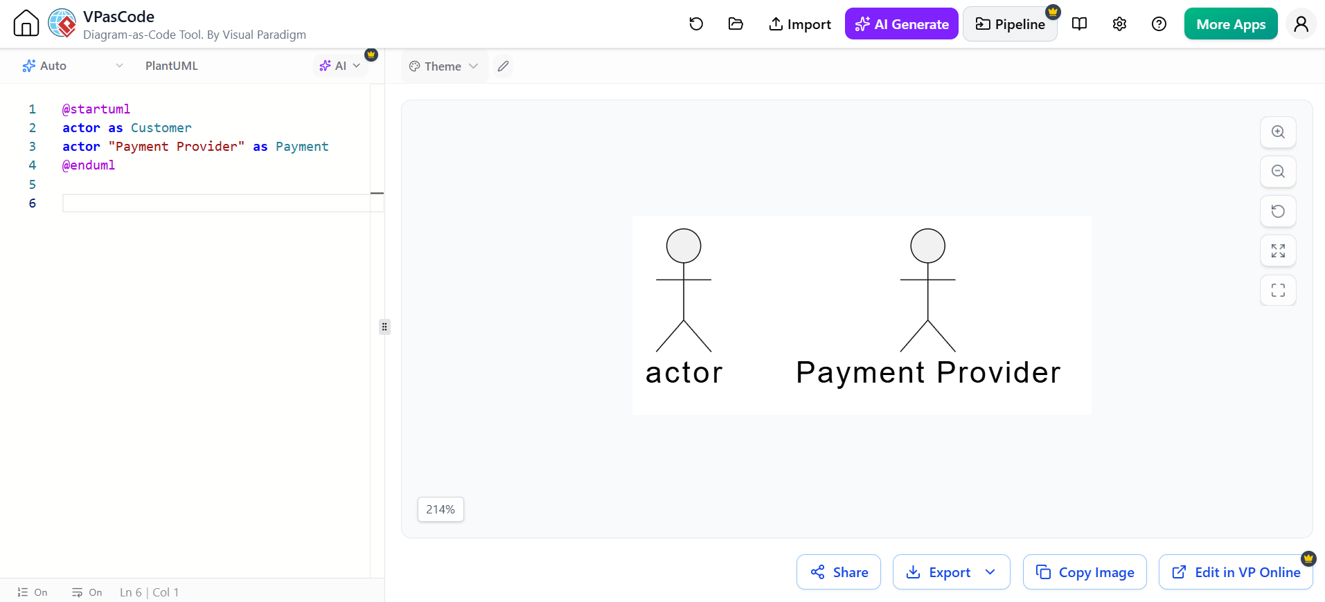
An actor is an external role interacting with the system. It may be a person, another system, device, or organization.
Typical examples:
-
Customer
-
Administrator
-
Mobile app
-
Payment provider
-
External API
PlantUML:
@startuml
actor Customer
actor "Payment Provider" as Payment
@enduml
Lifeline
A lifeline represents a participant in the interaction. It is drawn as a named head with a vertical dashed line beneath it.
Participants can represent:
-
Objects
-
Classes
-
Services
-
Databases
-
Queues
-
User interfaces
-
External systems
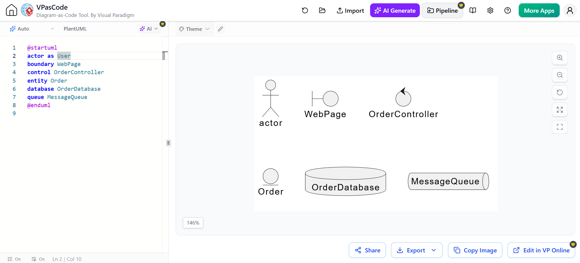
PlantUML supports different participant types:
@startuml
actor User
boundary WebPage
control OrderController
entity Order
database OrderDatabase
queue MessageQueue
@enduml
The participant keyword is generic, while specialized keywords communicate a participant’s role and affect its visual appearance.
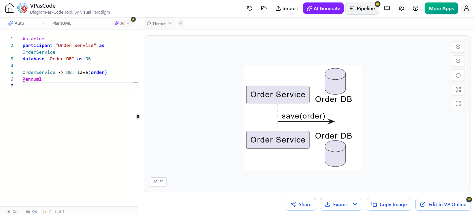
You can also use aliases to simplify message statements:
@startuml
participant "Order Service" as OrderService
database "Order DB" as DB

OrderService -> DB: save(order)
@enduml
Object notation
Objects may be shown by object name, object and class, or class name alone.
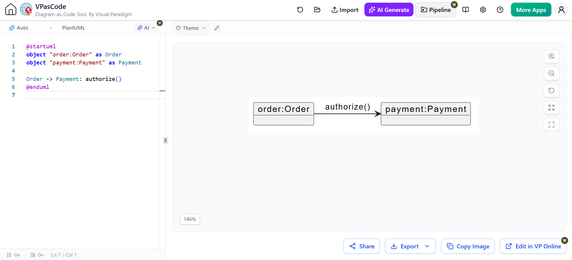
@startuml
object "order:Order" as Order
object "payment:Payment" as Payment

Order -> Payment: authorize()
@enduml
Time direction
Sequence diagrams are read from top to bottom:
Earlier interaction
        ↓
Later interaction
The horizontal axis generally identifies participants; the vertical axis establishes order.
2. Messages
A message represents communication between two lifelines. It may correspond to:
-
A method call
-
A function invocation
-
An HTTP request
-
A response
-
An event
-
A signal
-
A database operation
-
A message placed on a queue
The general PlantUML form is:
Example:
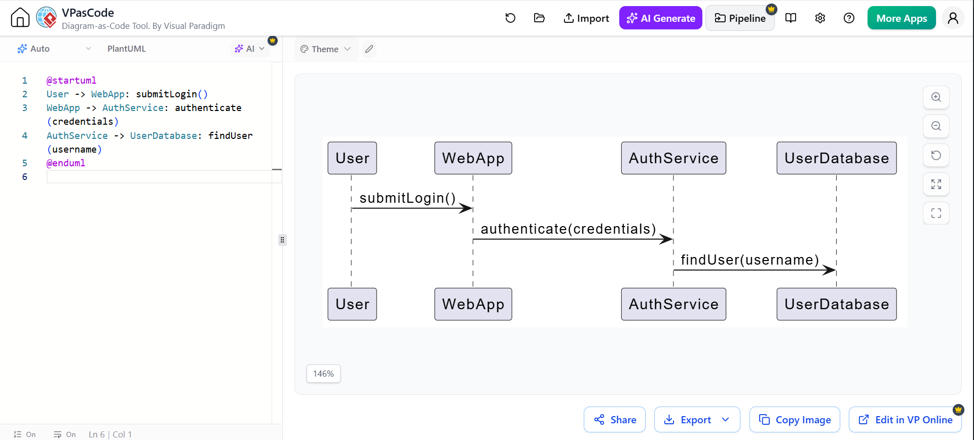
@startuml
User -> WebApp: submitLogin()
WebApp -> AuthService: authenticate(credentials)
AuthService -> UserDatabase: findUser(username)
@enduml
3. Message arrow types
PlantUML uses arrow syntax to distinguish message styles.
| PlantUML syntax | Typical meaning | UML interpretation |
|---|---|---|
A -> B |
Synchronous call | A invokes an operation on B |
A --> B |
Return or response | B returns information to A |
A ->> B |
Asynchronous call | A sends a signal or event without waiting |
A -->> B |
Asynchronous return or dashed response | A non-blocking response or notification |
A -\ B |
Half-arrow message | Event-style or one-way communication |
A ->x B |
Lost message | Message does not reach a known participant |
A ->o B |
Found message | Message originates outside the visible interaction |
The exact arrow style is partly a visual convention, so document your interpretation when precision matters. PlantUML’s standard syntax includes solid, dotted, open-headed, and reverse arrows.
Synchronous call and return
A synchronous call normally means the sender waits for the receiver to finish.
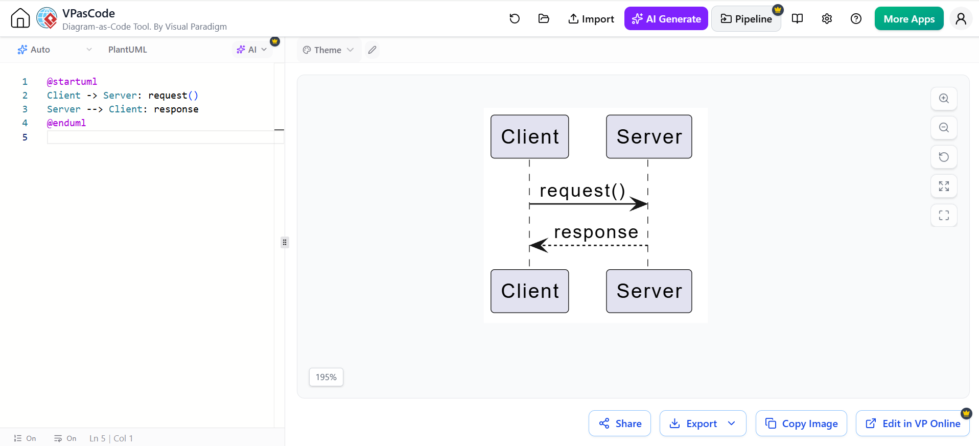
@startuml
Client -> Server: request()
Server --> Client: response
@enduml
Asynchronous message
An asynchronous message indicates that the sender does not necessarily wait for completion.
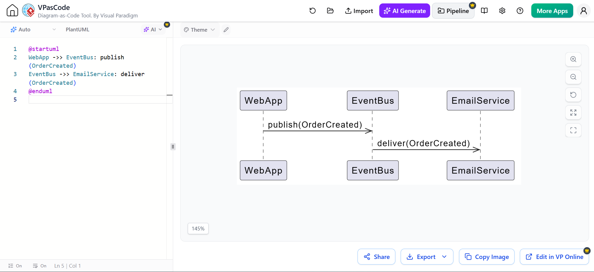
@startuml
WebApp ->> EventBus: publish(OrderCreated)
EventBus ->> EmailService: deliver(OrderCreated)
@enduml
Reverse-arrow notation
PlantUML supports reverse forms such as <- and <--. These can improve source-code readability without changing the visual direction of the message.
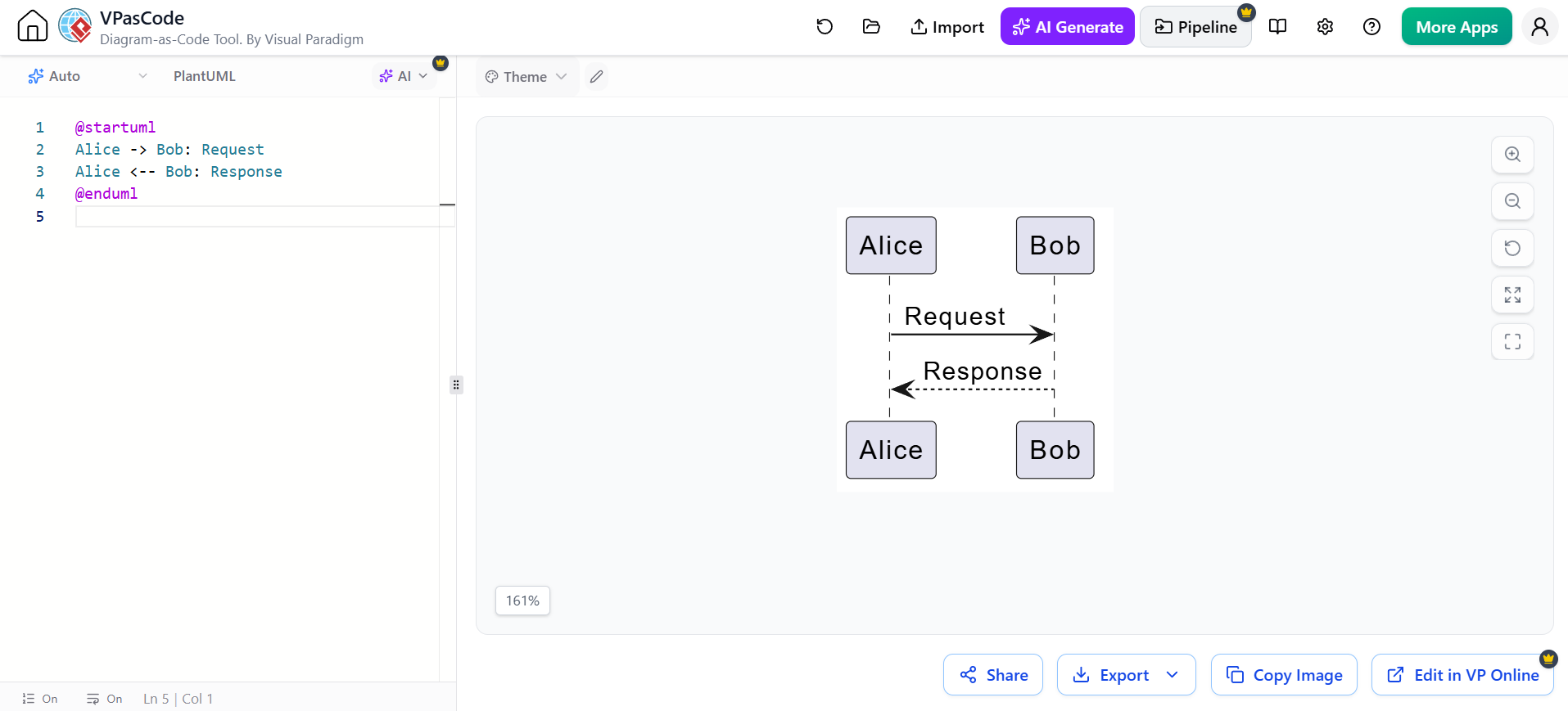
@startuml
Alice -> Bob: Request
Alice <-- Bob: Response
@enduml
Message labels
Use labels to describe intent rather than implementation details.
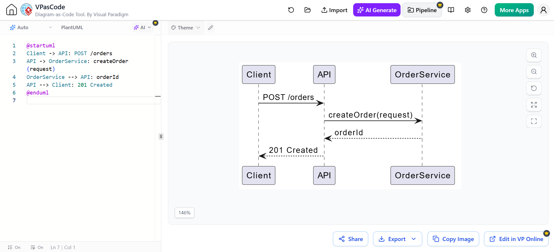
@startuml
Client -> API: POST /orders
API -> OrderService: createOrder(request)
OrderService --> API: orderId
API --> Client: 201 Created
@enduml
Good labels identify:
-
Operation name
-
Important parameters
-
Return values
-
HTTP method and endpoint
-
Event name
-
Business meaning
4. Activation bars
An activation, or execution specification, shows the period during which a participant is executing an operation. It is drawn as a narrow rectangle over the lifeline.
PlantUML can create activations explicitly:
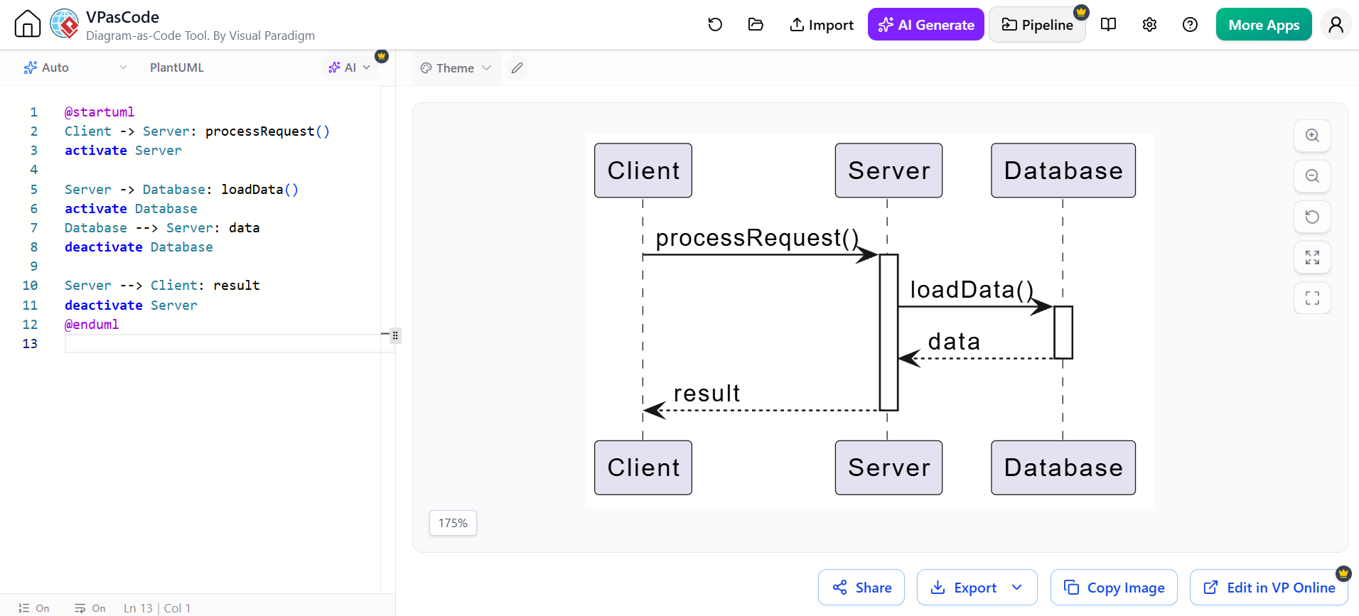
@startuml
Client -> Server: processRequest()
activate Server

Server -> Database: loadData()
activate Database
Database --> Server: data
deactivate Database

Server --> Client: result
deactivate Server
@enduml
A shorter form uses ++ and --:
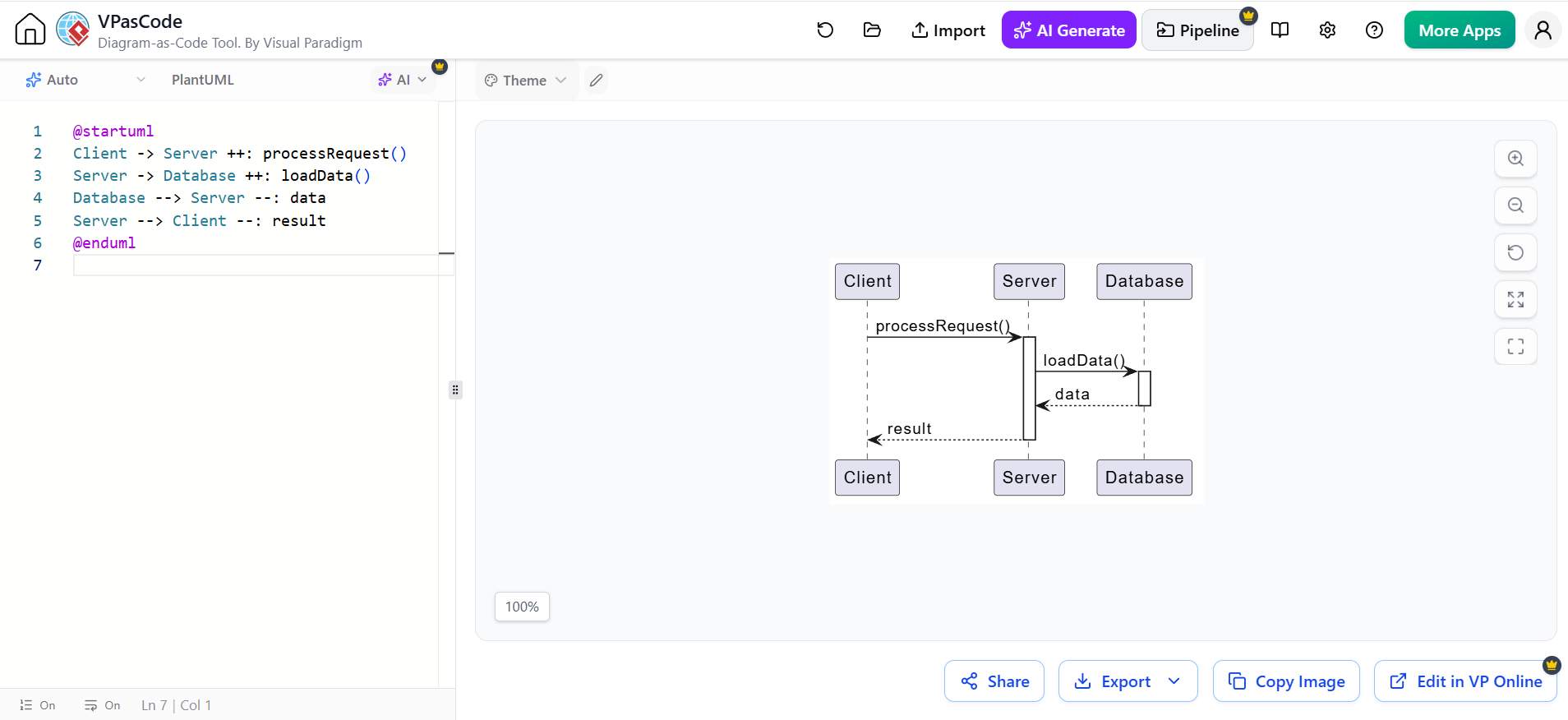
@startuml
Client -> Server ++: processRequest()
Server -> Database ++: loadData()
Database --> Server --: data
Server --> Client --: result
@enduml
Activations are useful for showing:
-
Nested calls
-
Responsibility
-
Call duration conceptually
-
Re-entrant operations
-
Which participant is active during a response
They should not be interpreted as exact performance measurements unless the diagram explicitly models timing.
5. Creation and destruction
Participant creation
A participant can be created during an interaction rather than existing from the beginning.
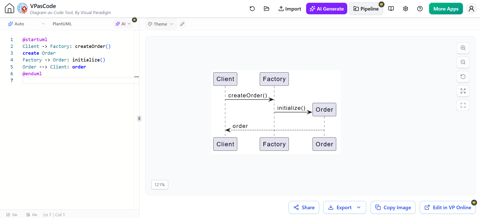
@startuml
Client -> Factory: createOrder()
create Order
Factory -> Order: initialize()
Order --> Client: order
@enduml
The create statement indicates that the participant comes into existence at that point.
Participant destruction
Use destroy when a participant is explicitly terminated or removed.
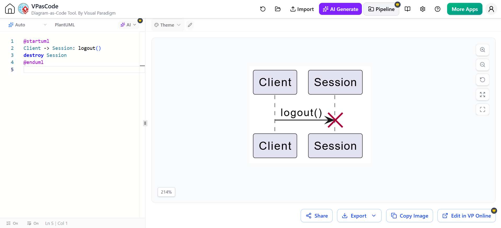
@startuml
Client -> Session: logout()
destroy Session
@enduml
Destruction is commonly used for:
-
Session termination
-
Object deletion
-
Process shutdown
-
Closing a connection
-
Cancelling a temporary resource
Do not use destruction merely because an operation has finished. Completion of a method is not the same as destruction of the participant.
6. Notes and comments
Notes add explanation without introducing another message.
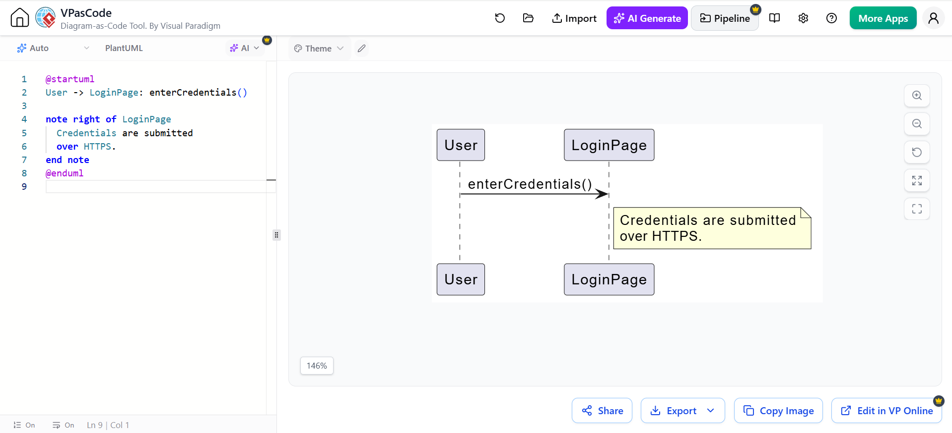
@startuml
User -> LoginPage: enterCredentials()

note right of LoginPage
  Credentials are submitted
  over HTTPS.
end note
@enduml
Other forms include:
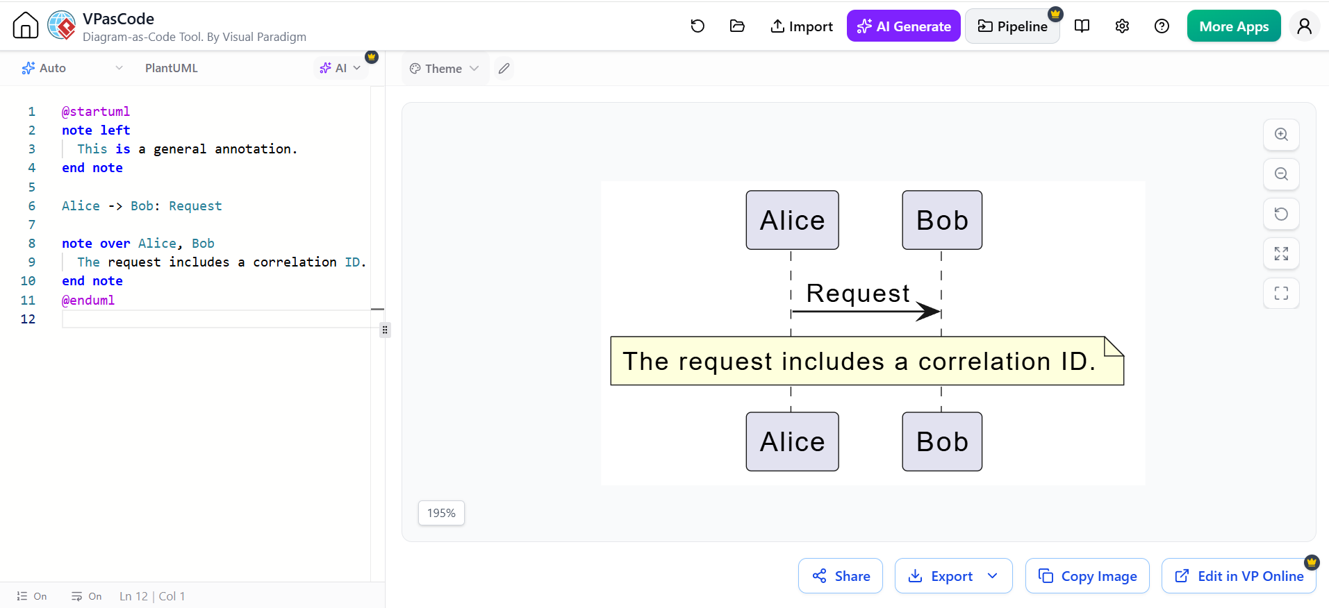
@startuml
note left
  This is a general annotation.
end note

Alice -> Bob: Request

note over Alice, Bob
  The request includes a correlation ID.
end note
@enduml
Notes are useful for:
-
Business rules
-
Security requirements
-
Assumptions
-
Error-handling explanations
-
Performance constraints
-
References to requirements or tickets
Avoid putting essential behavior only in notes. If something is part of the interaction, represent it as a message or fragment.
7. Combined fragments
A combined fragment is a frame around one or more interaction paths. The fragment operator appears in the upper-left corner.
The most important operators in the cheatsheet are alt, opt, loop, par, and ref.
alt: alternatives
Use alt for mutually exclusive branches, similar to if/else.
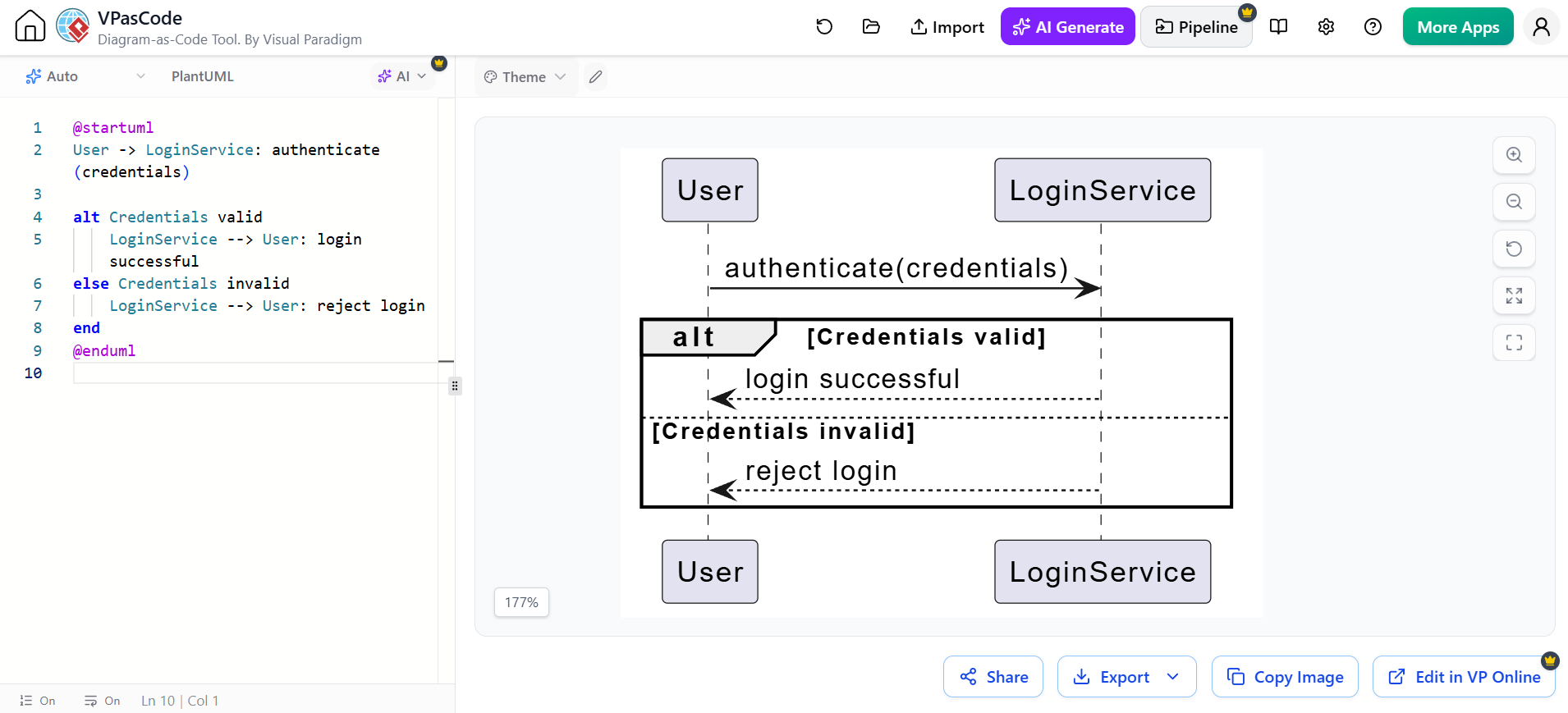
@startuml
User -> LoginService: authenticate(credentials)

alt Credentials valid
    LoginService --> User: login successful
else Credentials invalid
    LoginService --> User: reject login
end
@enduml
Meaning:
-
Exactly one branch executes.
-
Each branch has a guard or condition.
-
elseseparates alternatives.
opt: optional behavior
Use opt when a behavior occurs only if a condition is true and there is no meaningful alternative branch.
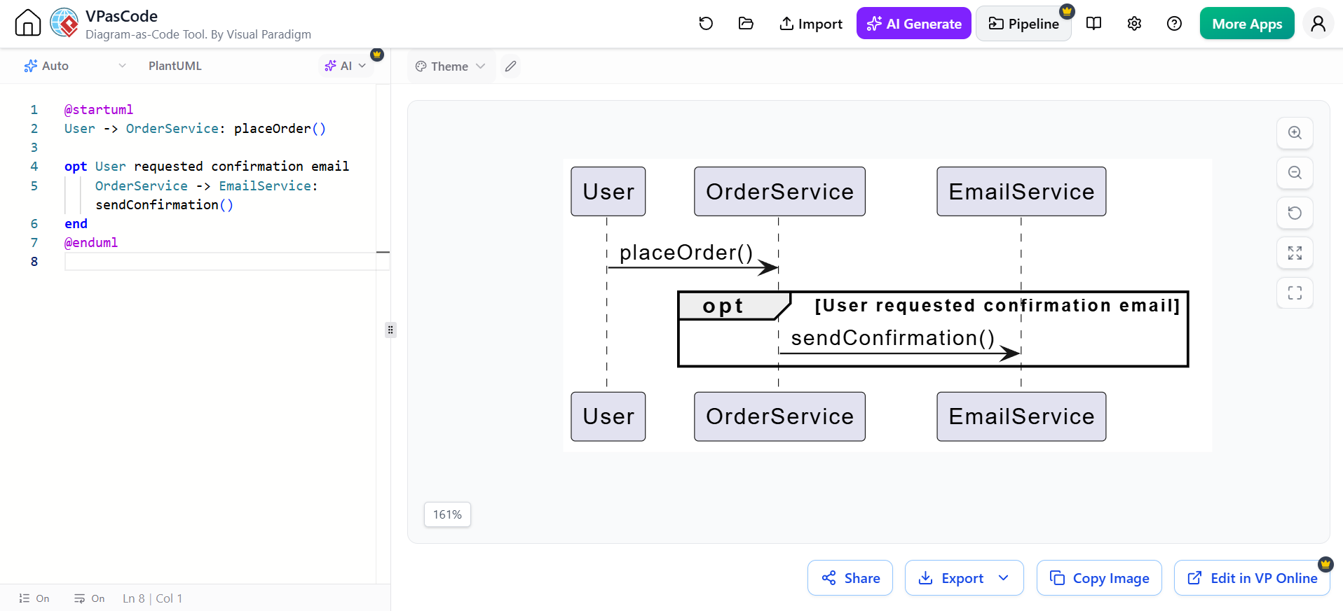
@startuml
User -> OrderService: placeOrder()

opt User requested confirmation email
    OrderService -> EmailService: sendConfirmation()
end
@enduml
opt is conceptually similar to an if without an else.
loop: repetition
Use loop for repeated behavior.
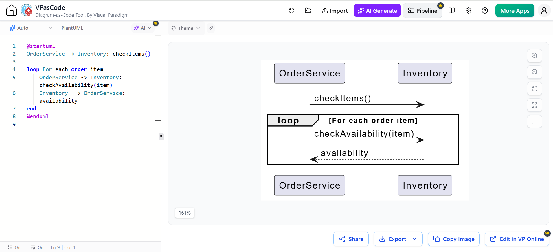
@startuml
OrderService -> Inventory: checkItems()

loop For each order item
    OrderService -> Inventory: checkAvailability(item)
    Inventory --> OrderService: availability
end
@enduml
You can specify a condition or limit:
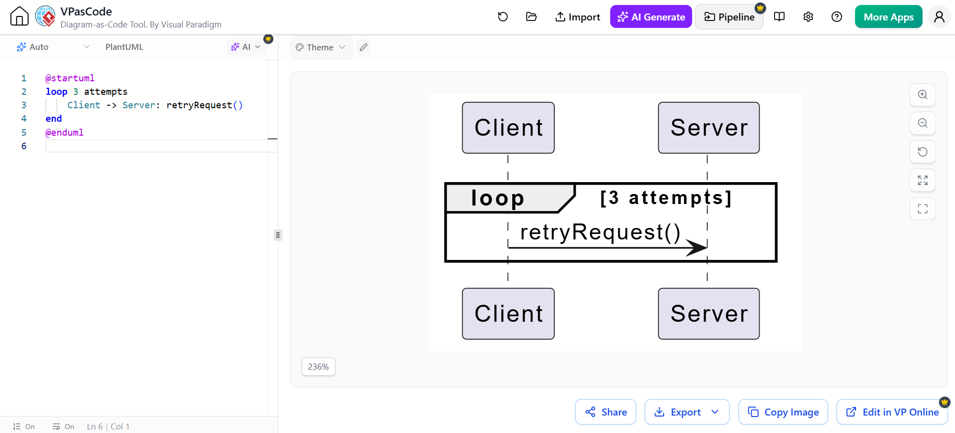
@startuml
loop 3 attempts
    Client -> Server: retryRequest()
end
@enduml
par: parallel behavior
Use par when interaction paths execute concurrently or independently.
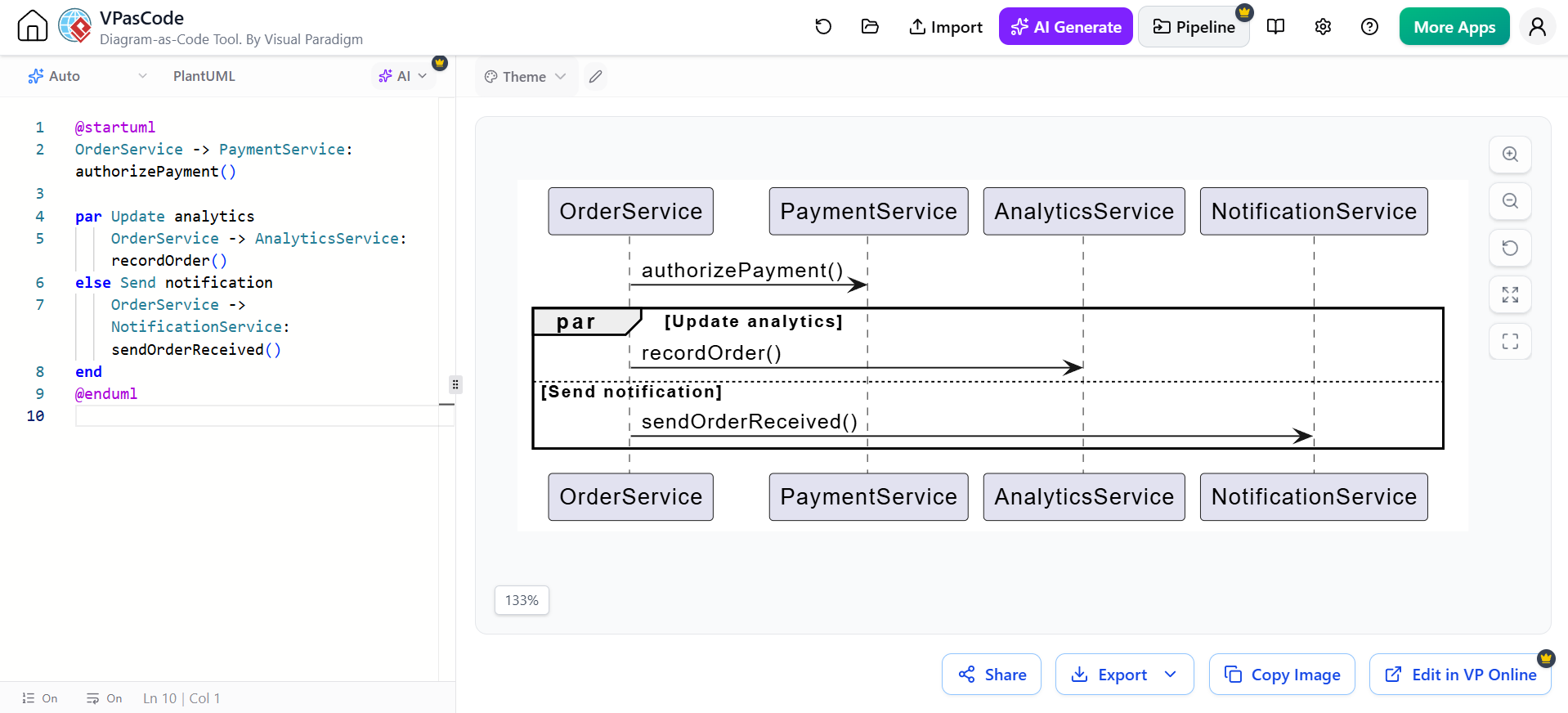
@startuml
OrderService -> PaymentService: authorizePayment()

par Update analytics
    OrderService -> AnalyticsService: recordOrder()
else Send notification
    OrderService -> NotificationService: sendOrderReceived()
end
@enduml
Use par only when parallelism is meaningful. If the operations simply happen in sequence, ordinary messages are clearer.
break: early termination
Use break when an error or condition ends the enclosing interaction.
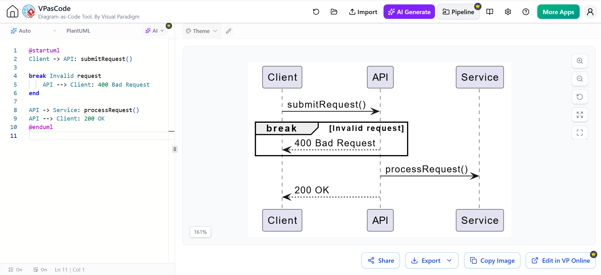
@startuml
Client -> API: submitRequest()

break Invalid request
    API --> Client: 400 Bad Request
end

API -> Service: processRequest()
API --> Client: 200 OK
@enduml
critical: critical region
A critical region identifies behavior that should execute atomically or under exclusive access.
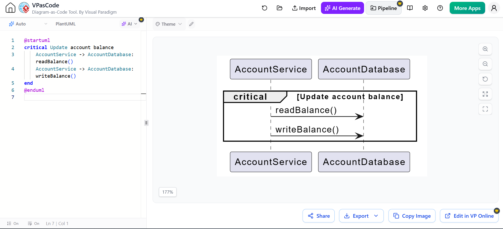
@startuml
critical Update account balance
    AccountService -> AccountDatabase: readBalance()
    AccountService -> AccountDatabase: writeBalance()
end
@enduml
group: invalid or forbidden interaction
Use neg to document behavior that must not occur.
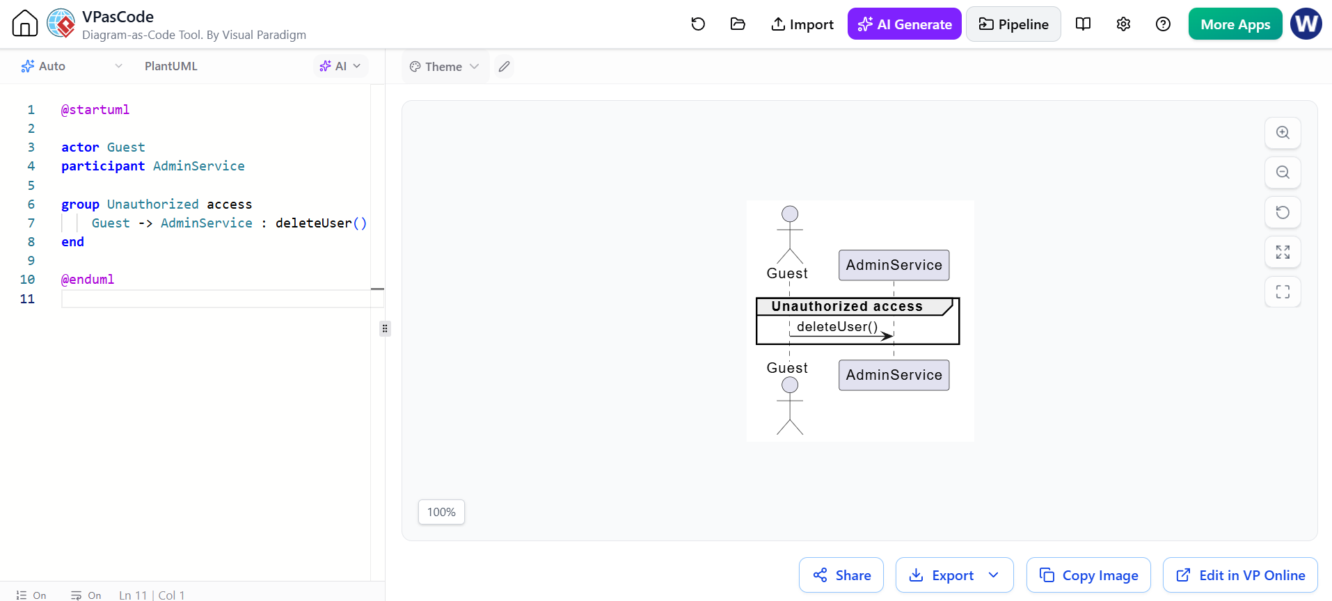
@startuml
group Unauthorized access
    Guest -> AdminService: deleteUser()
end
@enduml
ref: interaction reference
Use ref to refer to another sequence diagram or reusable interaction.
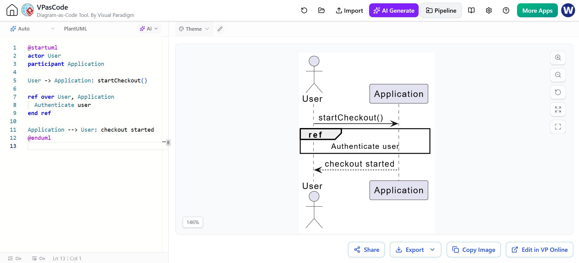
@startuml
actor User
participant Application

User -> Application: startCheckout()

ref over User, Application
  Authenticate user
end ref

Application --> User: checkout started
@enduml
Combined fragments are the standard way to represent branches, loops, parallel paths, optional behavior, references, and exceptional flows.
8. Guards and conditions
A guard is a condition controlling whether an interaction path executes.
Examples:
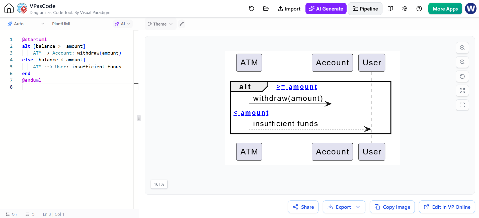
@startuml
alt [balance >= amount]
    ATM -> Account: withdraw(amount)
else [balance < amount]
    ATM --> User: insufficient funds
end
@enduml
In explanatory diagrams, descriptive guards are often easier to understand:
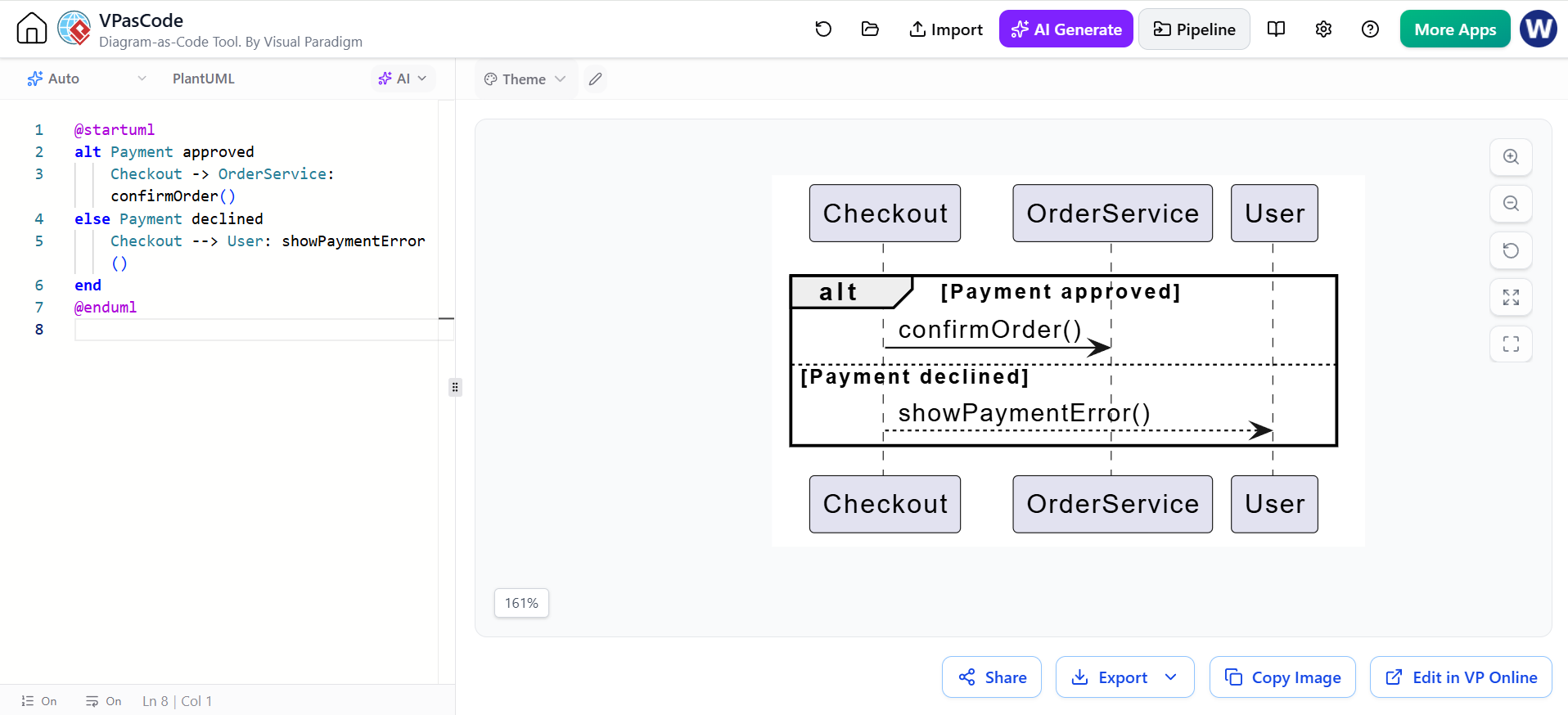
@startuml
alt Payment approved
    Checkout -> OrderService: confirmOrder()
else Payment declined
    Checkout --> User: showPaymentError()
end
@enduml
Use guards that are:
-
Short
-
Business-relevant
-
Mutually understandable
-
Consistent with the system’s terminology
9. Interaction operators in the cheatsheet
The cheatsheet includes several common UML operators:
| Operator | Purpose | Typical code equivalent |
|---|---|---|
alt |
Multiple alternative paths | if / else if / else |
opt |
Optional path | if |
loop |
Repeated interaction | for, while, retry |
par |
Concurrent paths | Parallel tasks or threads |
break |
Stop the interaction early | Exception, rejection, cancellation |
critical |
Exclusive or atomic region | Lock or transaction |
neg |
Invalid interaction | Forbidden behavior |
assert |
Required interaction | Invariant or precondition |
ref |
Reuse another interaction | Called or referenced scenario |
10. Sequence numbering
Sequence numbers are optional because vertical order already conveys the basic sequence. They are useful when discussing a diagram in meetings, specifications, or test cases.
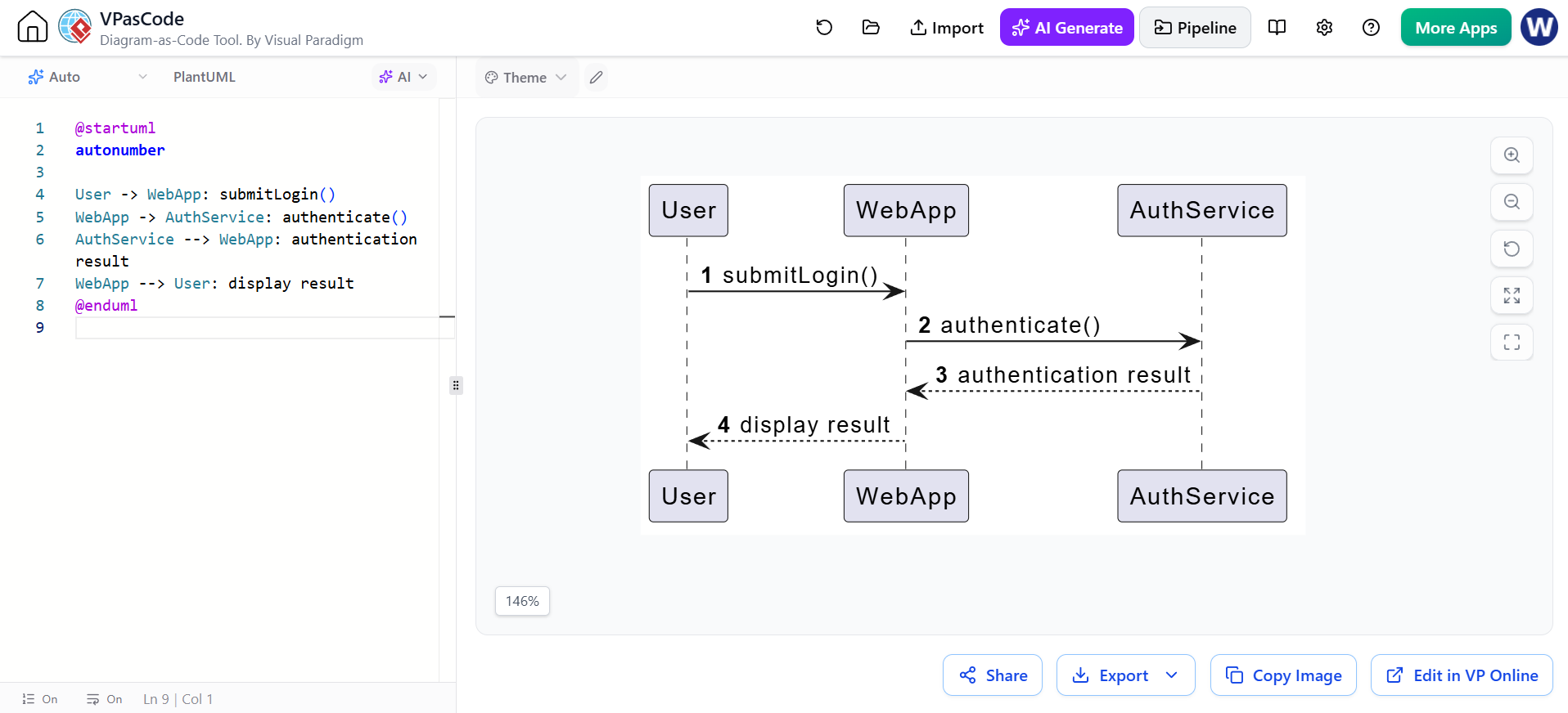
@startuml
autonumber

User -> WebApp: submitLogin()
WebApp -> AuthService: authenticate()
AuthService --> WebApp: authentication result
WebApp --> User: display result
@enduml
Start at a custom number:
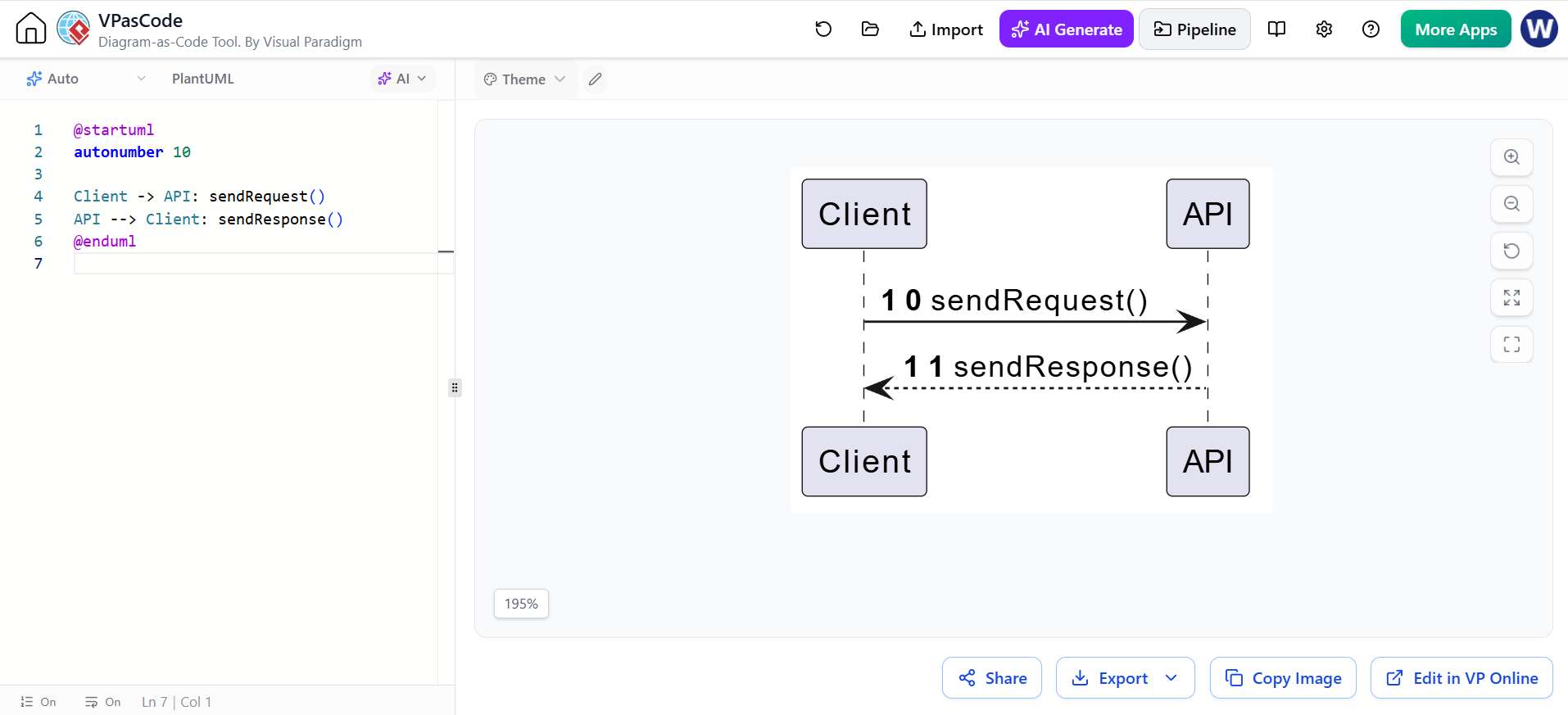
@startuml
autonumber 10

Client -> API: sendRequest()
API --> Client: sendResponse()
@enduml
Use an increment:
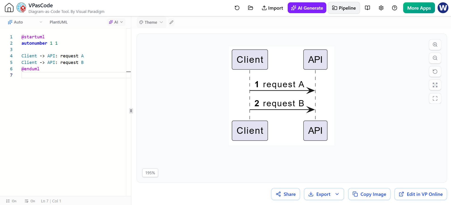
@startuml
autonumber 1 1

Client -> API: request A
Client -> API: request B
@enduml
PlantUML also supports stopping and resuming automatic numbering.
11. Grouping and visual organization
Group
Use group to visually group related messages.
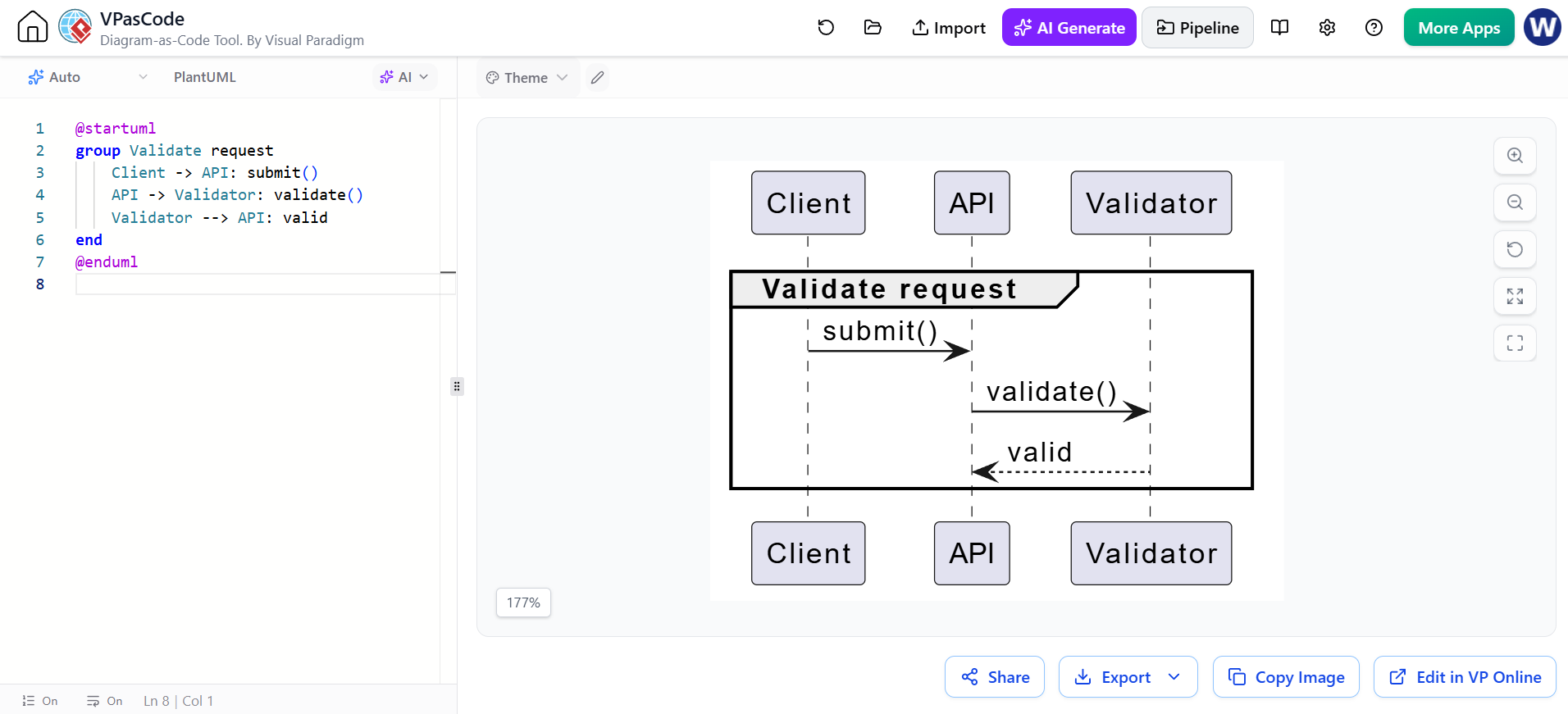
@startuml
group Validate request
    Client -> API: submit()
    API -> Validator: validate()
    Validator --> API: valid
end
@enduml
Box
Use box to group participants visually.
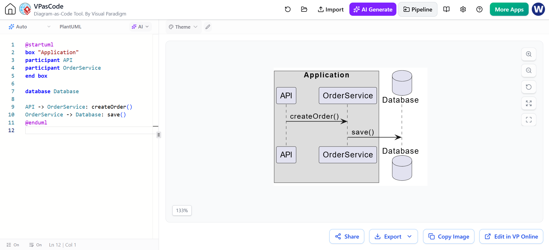
@startuml
box "Application"
participant API
participant OrderService
end box

database Database

API -> OrderService: createOrder()
OrderService -> Database: save()
@enduml
Separators
Separators can divide phases of a scenario:
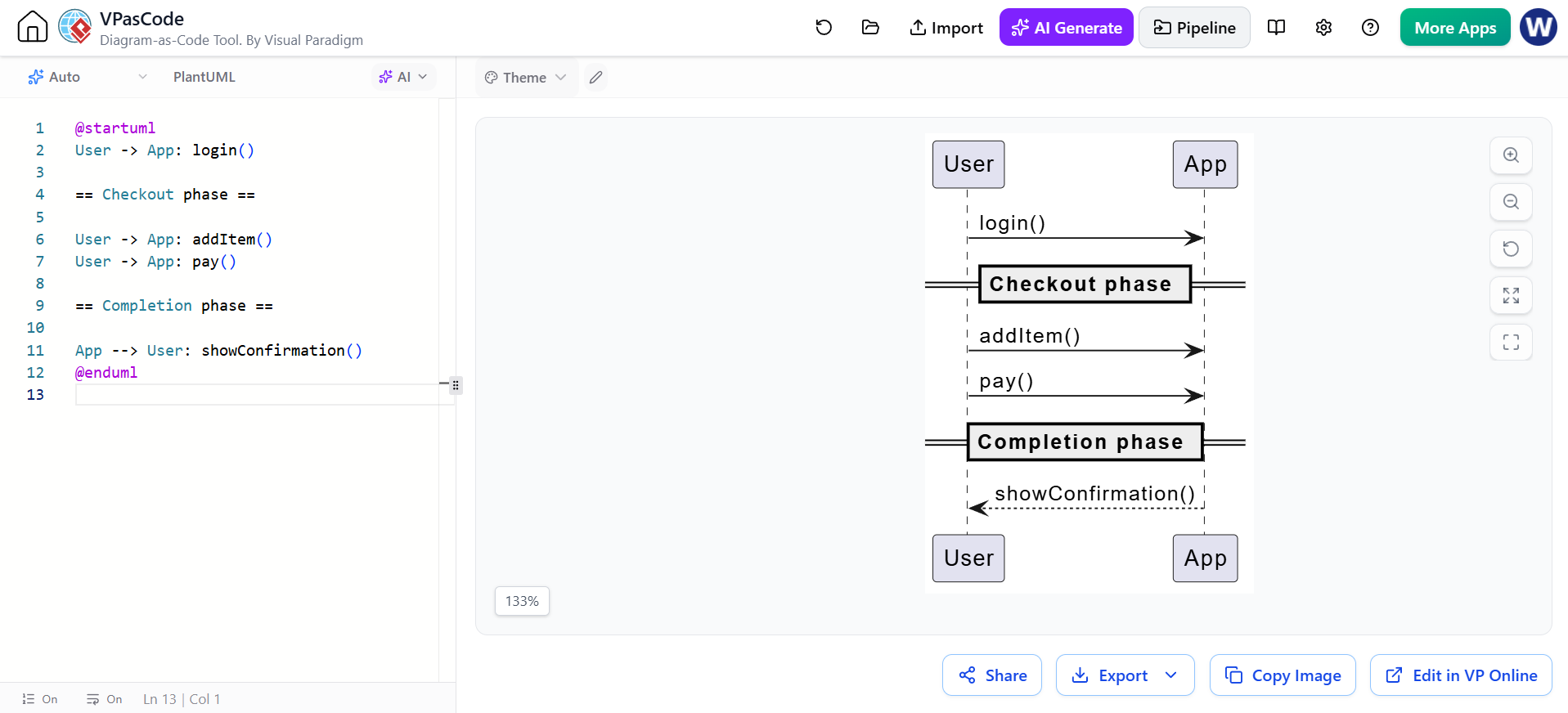
@startuml
User -> App: login()

== Checkout phase ==

User -> App: addItem()
User -> App: pay()

== Completion phase ==

App --> User: showConfirmation()
@enduml
12. Reference interaction example: authentication
The following example combines actors, participants, activations, returns, alternatives, and numbering.
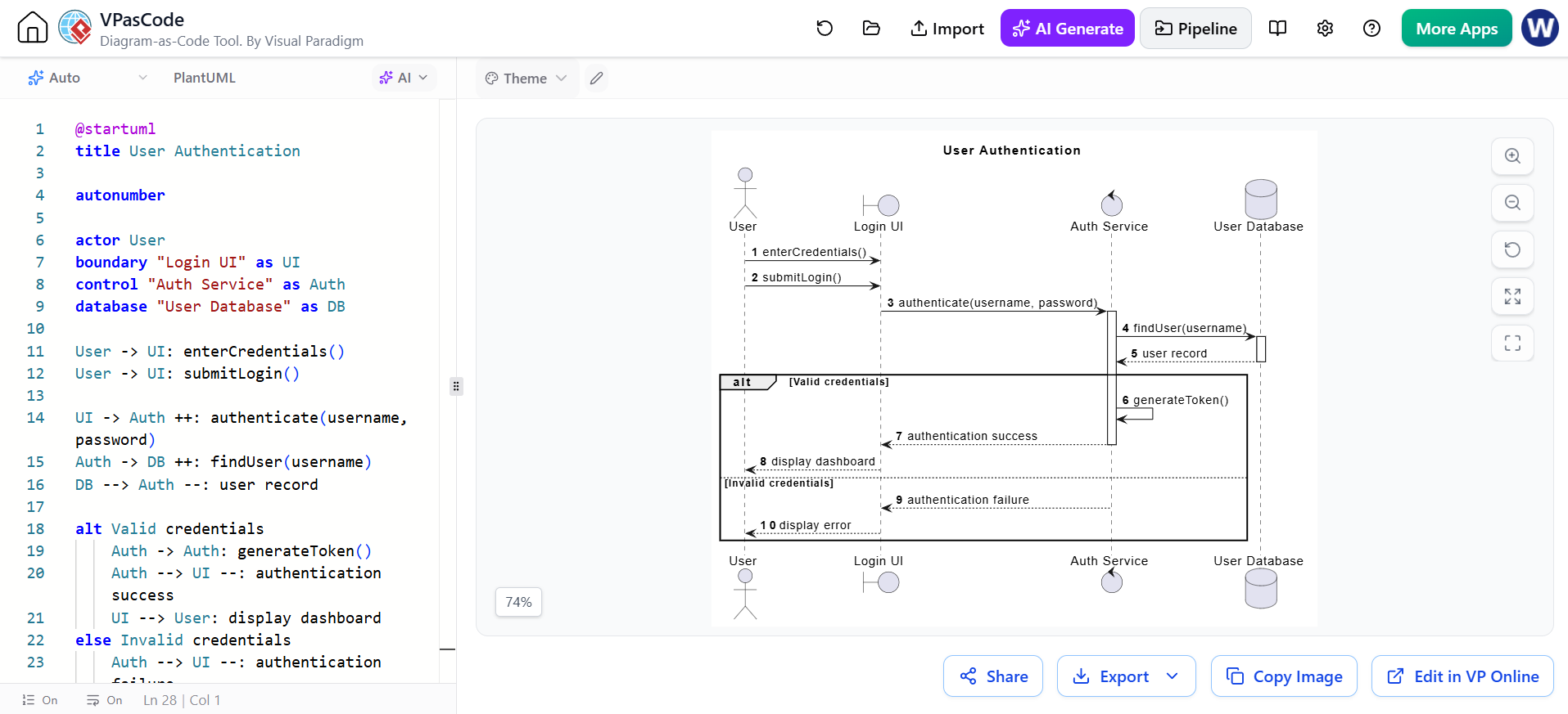
@startuml
title User Authentication

autonumber

actor User
boundary "Login UI" as UI
control "Auth Service" as Auth
database "User Database" as DB

User -> UI: enterCredentials()
User -> UI: submitLogin()

UI -> Auth ++: authenticate(username, password)
Auth -> DB ++: findUser(username)
DB --> Auth --: user record

alt Valid credentials
    Auth -> Auth: generateToken()
    Auth --> UI --: authentication success
    UI --> User: display dashboard
else Invalid credentials
    Auth --> UI --: authentication failure
    UI --> User: display error
end

@enduml
Concepts demonstrated:
-
actor -
boundary -
control -
database -
autonumber -
Nested activations
-
Return messages
-
Self-message
-
altandelse -
Explicit response behavior
13. Reference interaction example: online checkout
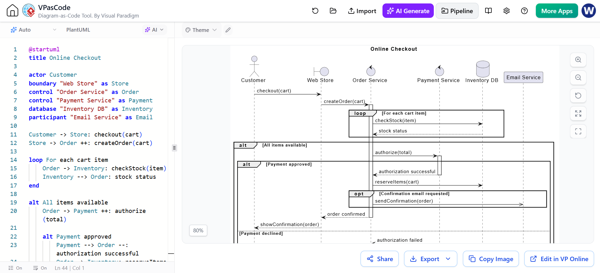
@startuml
title Online Checkout

actor Customer
boundary "Web Store" as Store
control "Order Service" as Order
control "Payment Service" as Payment
database "Inventory DB" as Inventory
participant "Email Service" as Email

Customer -> Store: checkout(cart)
Store -> Order ++: createOrder(cart)

loop For each cart item
    Order -> Inventory: checkStock(item)
    Inventory --> Order: stock status
end

alt All items available
    Order -> Payment ++: authorize(total)

    alt Payment approved
        Payment --> Order --: authorization successful
        Order -> Inventory: reserveItems(cart)

        opt Confirmation email requested
            Order ->> Email: sendConfirmation(order)
        end

        Order --> Store --: order confirmed
        Store --> Customer: showConfirmation(order)
    else Payment declined
        Payment --> Order --: authorization failed
        Order --> Store --: payment error
        Store --> Customer: showPaymentError()
    end

else Item unavailable
    Order --> Store: unavailable item
    Store --> Customer: showStockError()
end

@enduml
This illustrates:
-
Nested
altfragments -
A
loop -
An
optfragment -
Asynchronous notification
-
Database interaction
-
Service activations
-
Business-level outcomes
14. Self-messages
A participant can send a message to itself. This is useful for internal computation or delegation.
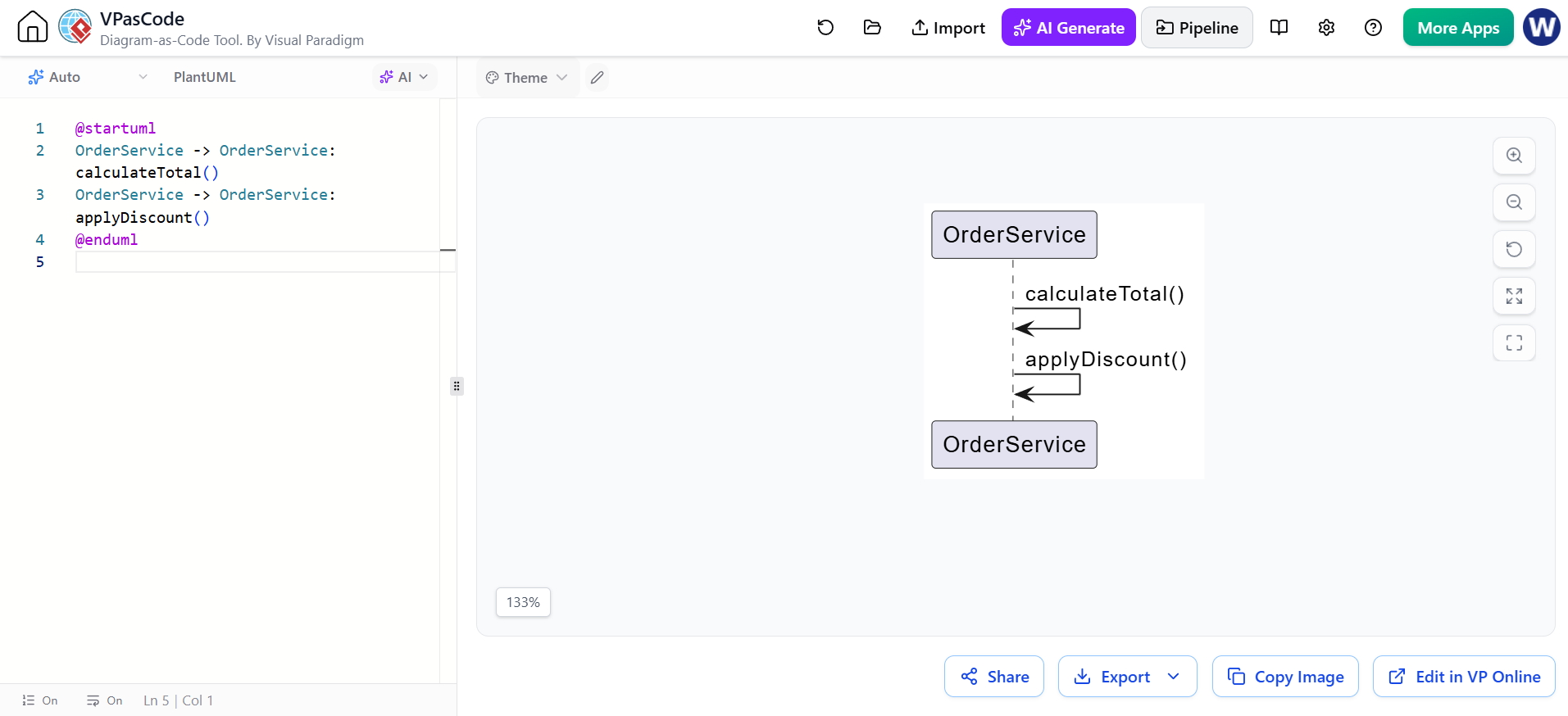
@startuml
OrderService -> OrderService: calculateTotal()
OrderService -> OrderService: applyDiscount()
@enduml
Self-messages should be used selectively. If the internal details are not relevant to the scenario, omit them.
15. Return messages
A return message commonly uses a dashed line:
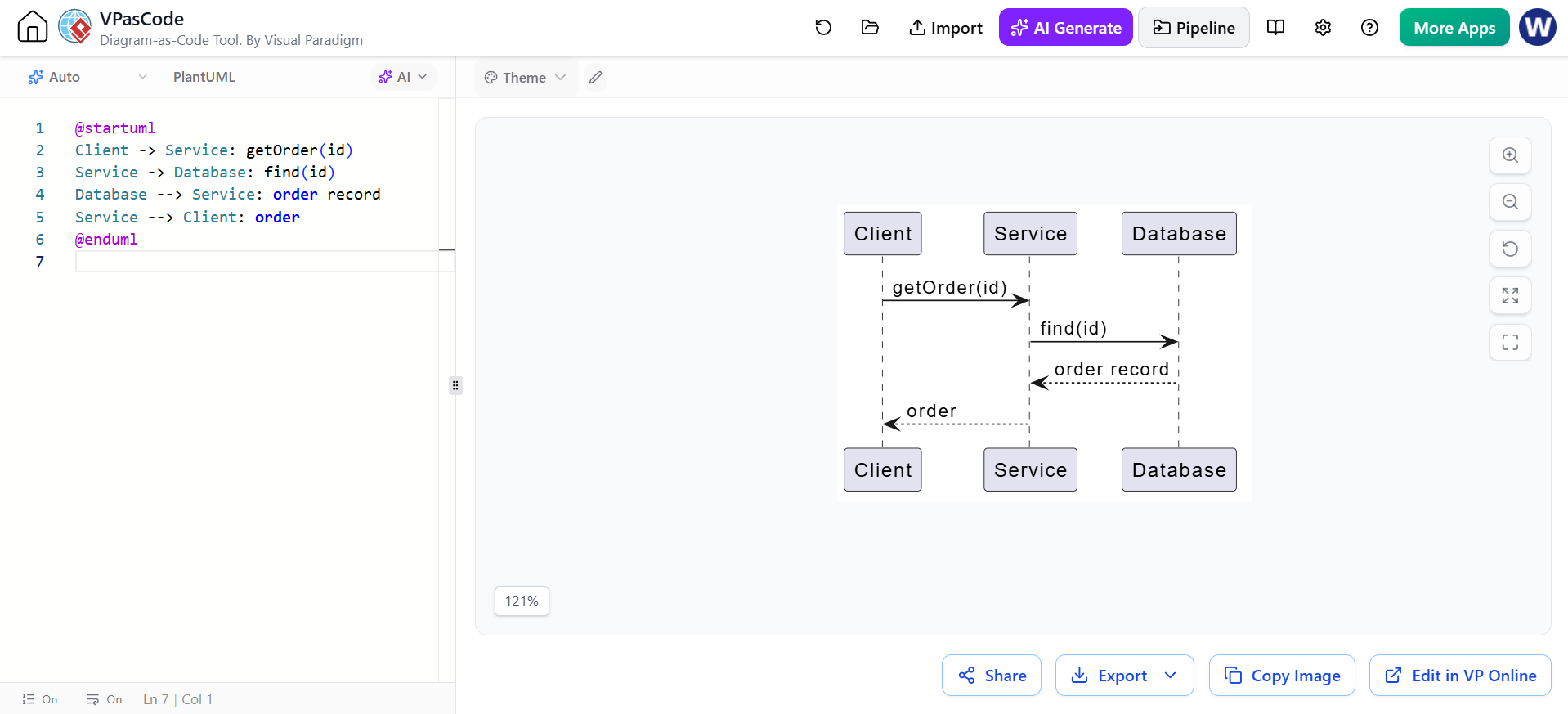
@startuml
Client -> Service: getOrder(id)
Service -> Database: find(id)
Database --> Service: order record
Service --> Client: order
@enduml
You do not need to draw every return. Include returns when they help explain:
-
A meaningful result
-
A status
-
A decision
-
An error
-
Data passed back to the caller
Avoid cluttering simple diagrams with trivial returns.
16. Lost and found messages
A lost message leaves a participant but does not arrive at a visible participant:
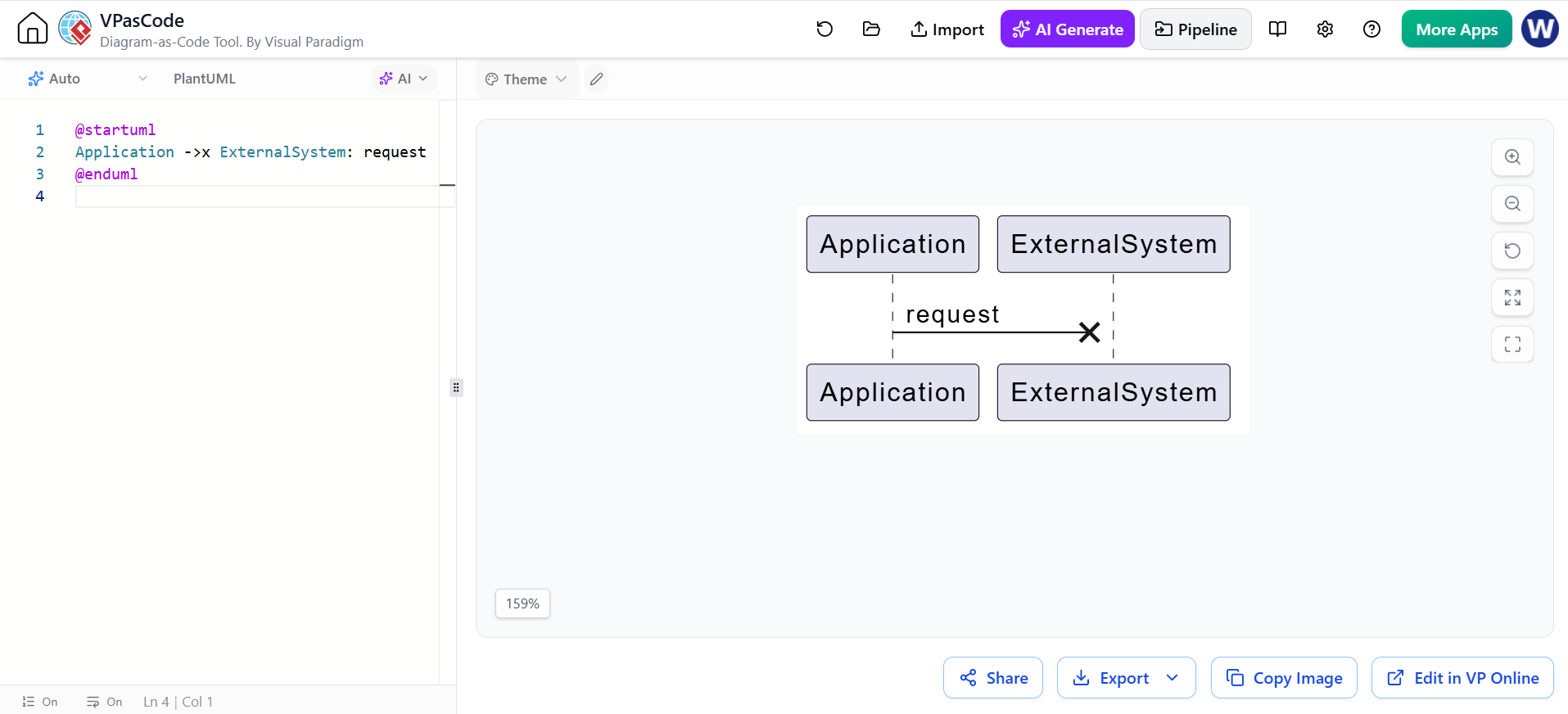
@startuml
Application ->x ExternalSystem: request
@enduml
A found message enters the diagram from an unknown source:
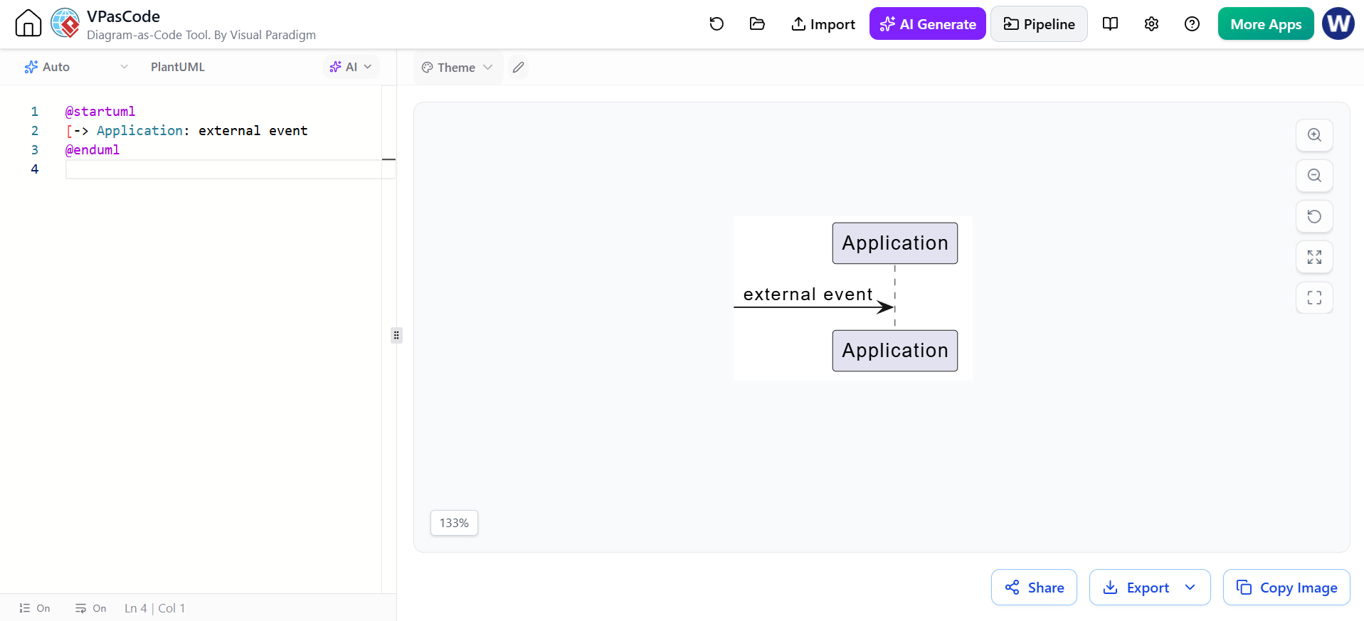
@startuml
[-> Application: external event
@enduml
These are useful for representing:
-
Network failures
-
Dropped events
-
External triggers
-
Unmodeled system boundaries
17. Colors and styling
PlantUML permits individual arrow colors:
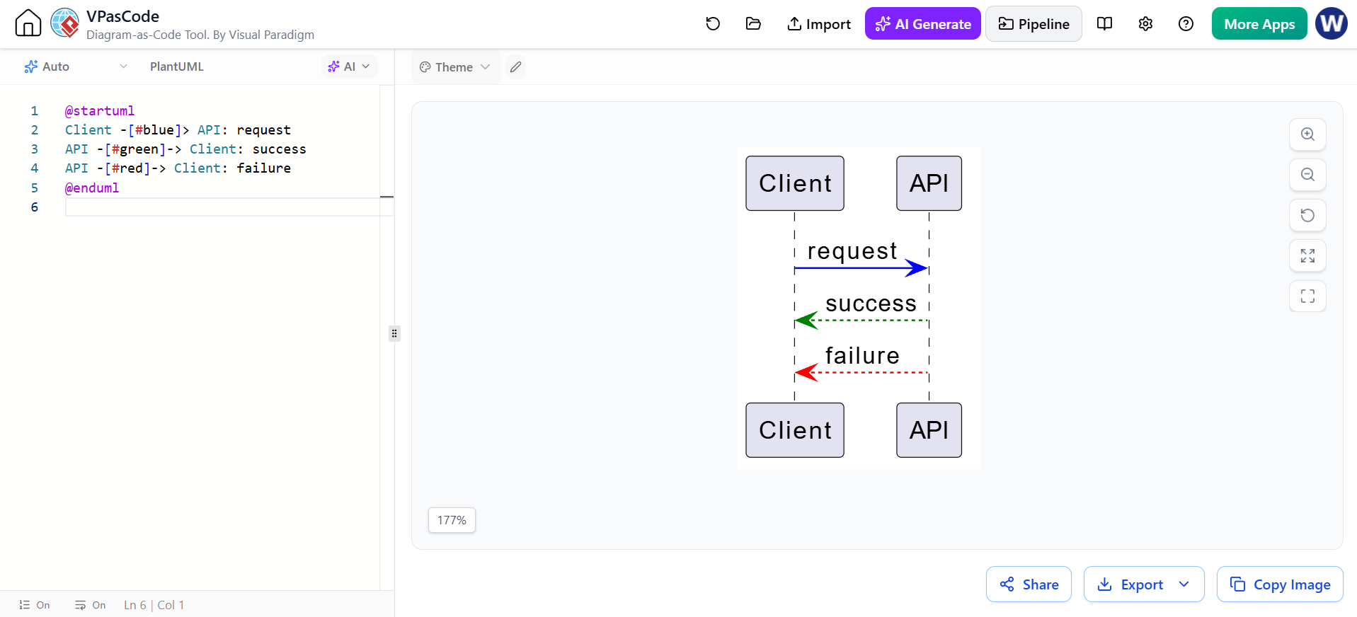
@startuml
Client -[#blue]> API: request
API -[#green]-> Client: success
API -[#red]-> Client: failure
@enduml
You can also style participants:
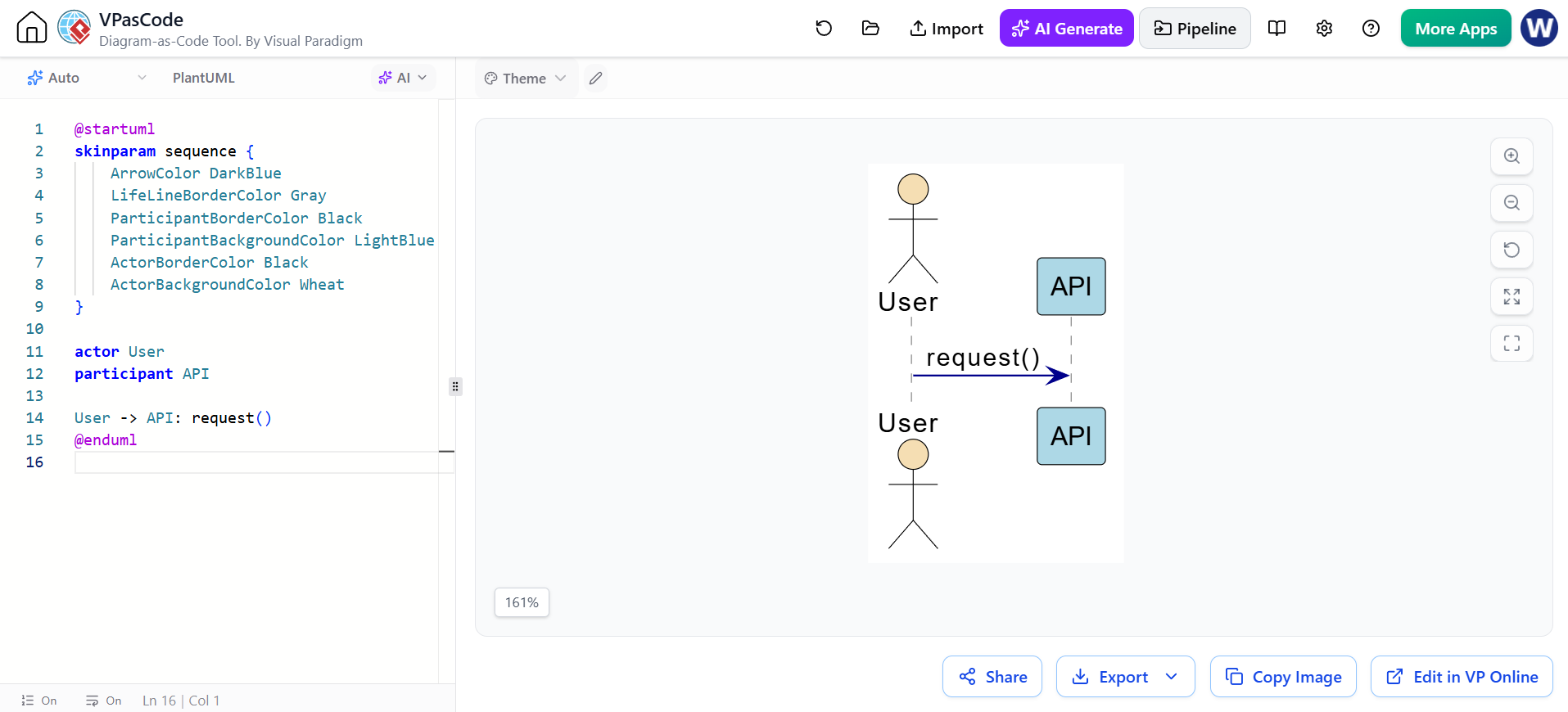
@startuml
skinparam sequence {
    ArrowColor DarkBlue
    LifeLineBorderColor Gray
    ParticipantBorderColor Black
    ParticipantBackgroundColor LightBlue
    ActorBorderColor Black
    ActorBackgroundColor Wheat
}

actor User
participant API

User -> API: request()
@enduml
Use color sparingly:
-
Red for failures or prohibited actions
-
Green for success
-
Blue for ordinary requests
-
Gray for background or infrastructure behavior
Do not make color the only way to distinguish outcomes; labels should remain understandable in grayscale.
18. Lifeline ordering
Participants are normally displayed in declaration order:
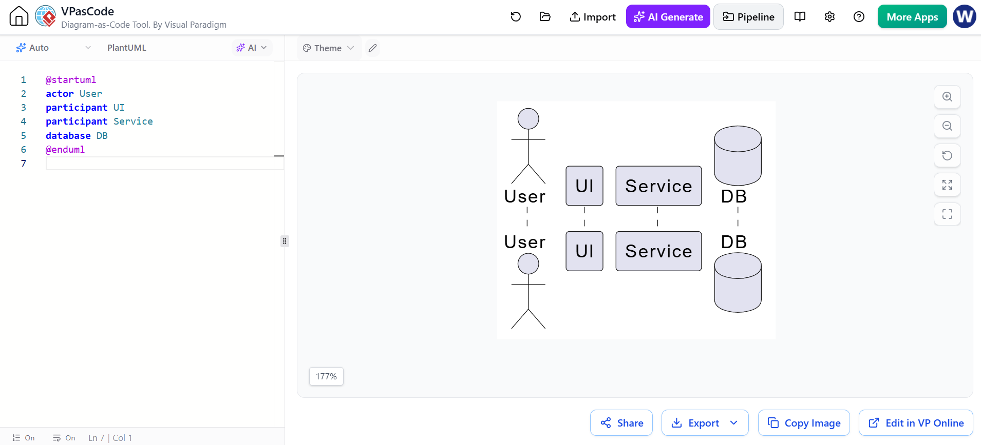
@startuml
actor User
participant UI
participant Service
database DB
@enduml
This produces a natural left-to-right flow:
User → UI → Service → DB
You can control ordering by declaring participants before messages:
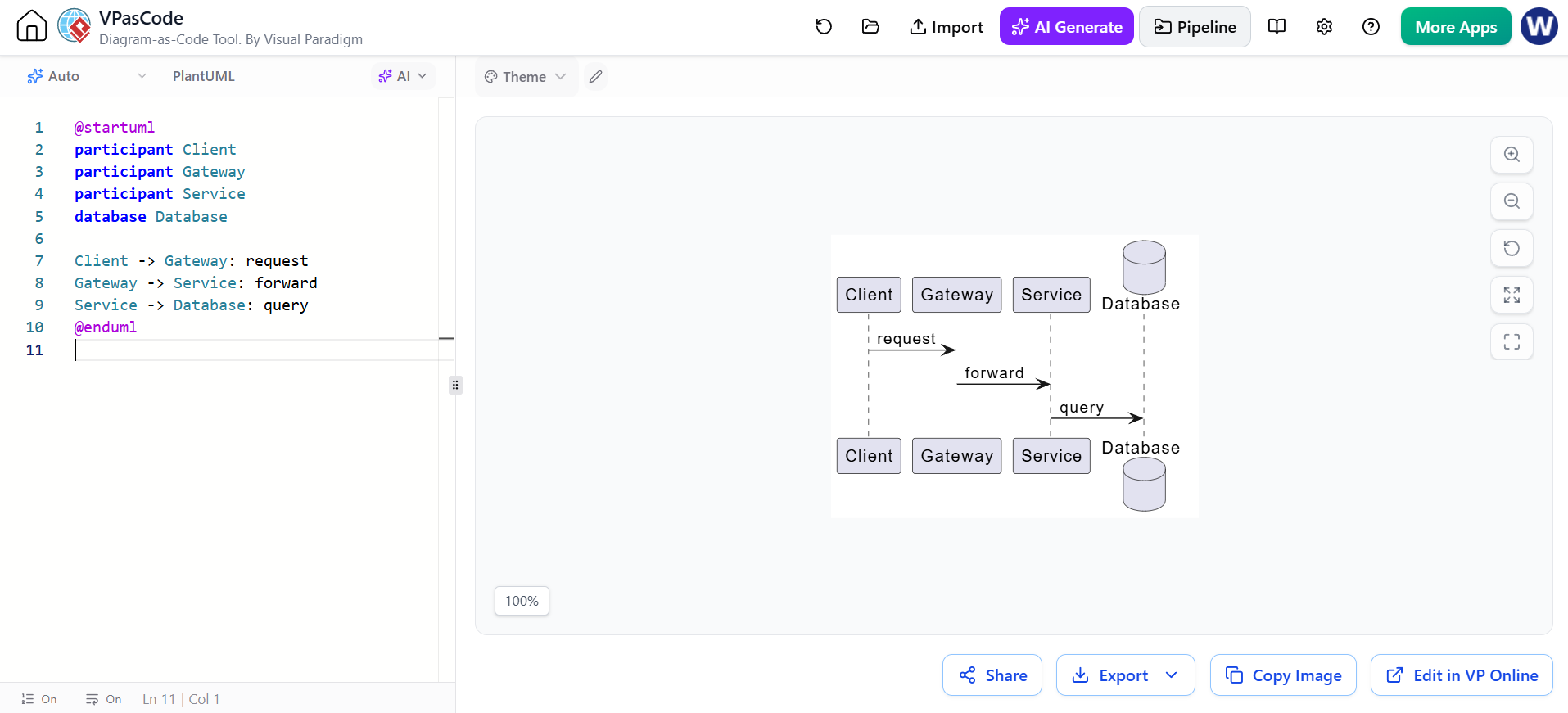
@startuml
participant Client
participant Gateway
participant Service
database Database

Client -> Gateway: request
Gateway -> Service: forward
Service -> Database: query
@enduml
A good ordering generally follows the dominant communication path, but avoid rearranging participants merely to make one unusual message shorter.
19. Boundary, control, entity, and database stereotypes
The following participant categories are especially common in analysis and design diagrams:
| Type | Typical responsibility |
|---|---|
boundary |
User interface or system boundary |
control |
Coordinates a use case or workflow |
entity |
Business data or domain object |
database |
Persistent storage |
actor |
External role |
queue |
Asynchronous message buffer |
collections |
Collection or group of objects |
Example:
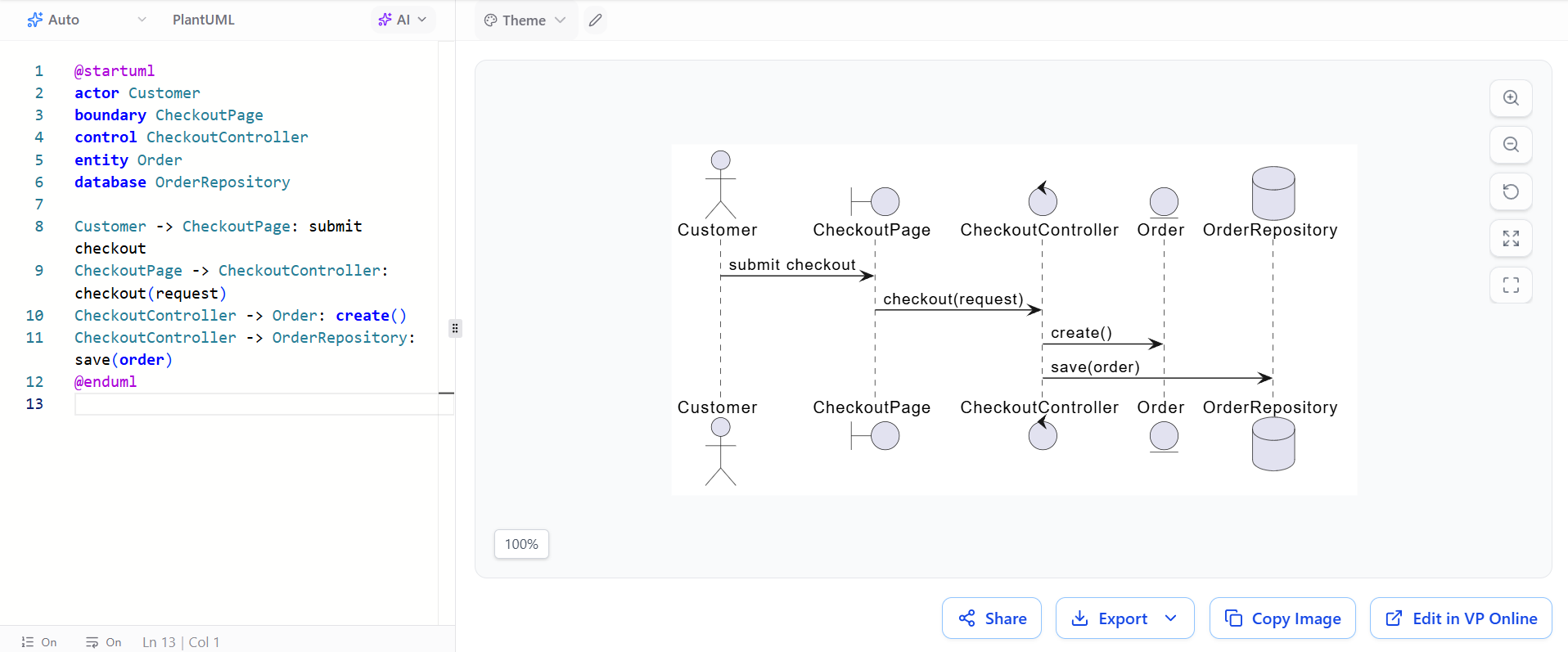
@startuml
actor Customer
boundary CheckoutPage
control CheckoutController
entity Order
database OrderRepository

Customer -> CheckoutPage: submit checkout
CheckoutPage -> CheckoutController: checkout(request)
CheckoutController -> Order: create()
CheckoutController -> OrderRepository: save(order)
@enduml
20. Modeling system-level versus design-level diagrams
System-level sequence diagram
Focuses on external actors and the system as a whole.
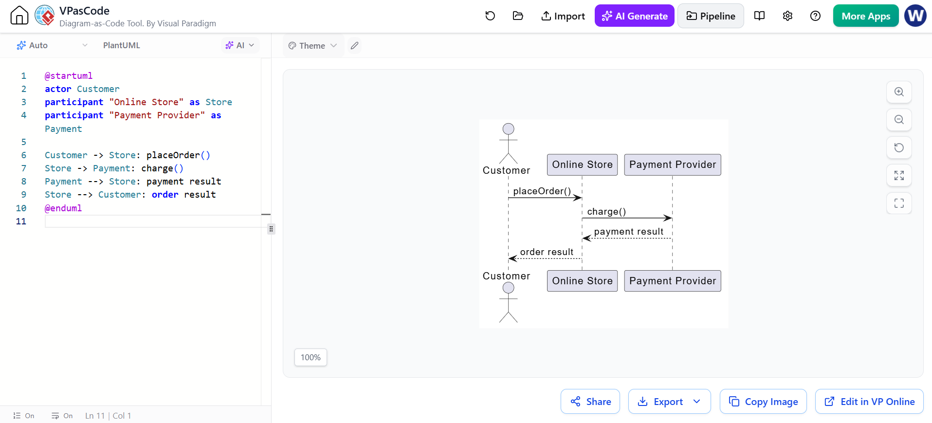
@startuml
actor Customer
participant "Online Store" as Store
participant "Payment Provider" as Payment

Customer -> Store: placeOrder()
Store -> Payment: charge()
Payment --> Store: payment result
Store --> Customer: order result
@enduml
Use this level for:
-
Requirements
-
Use-case scenarios
-
Stakeholder discussions
-
Product behavior
Design-level sequence diagram
Shows internal components and services.
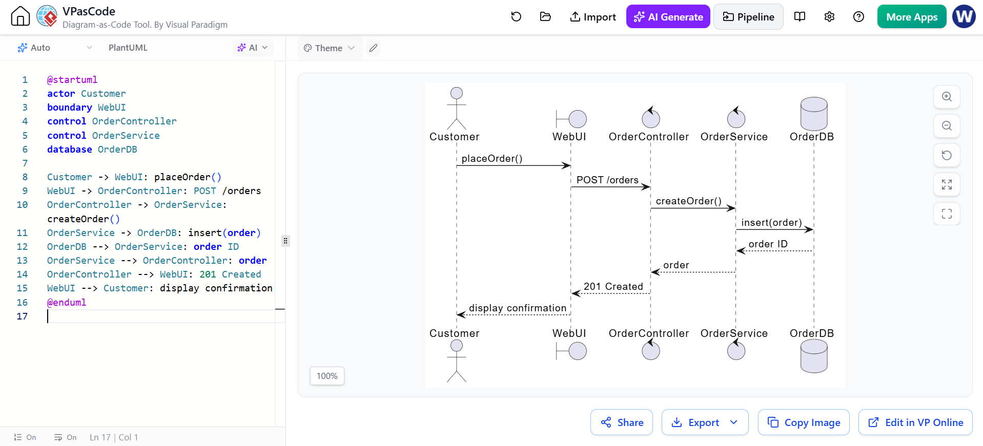
@startuml
actor Customer
boundary WebUI
control OrderController
control OrderService
database OrderDB

Customer -> WebUI: placeOrder()
WebUI -> OrderController: POST /orders
OrderController -> OrderService: createOrder()
OrderService -> OrderDB: insert(order)
OrderDB --> OrderService: order ID
OrderService --> OrderController: order
OrderController --> WebUI: 201 Created
WebUI --> Customer: display confirmation
@enduml
Use this level for:
-
API design
-
Service decomposition
-
Implementation planning
-
Debugging
-
Technical documentation
Do not mix abstraction levels unnecessarily. A diagram that shows both “customer clicks button” and highly detailed SQL statements may become difficult to read.
21. Sequence diagram design process
A practical workflow is:
-
Choose one scenario.
For example, “successful login” or “payment declined.” -
Identify the initiating actor.
Determine who or what starts the interaction. -
List the participants.
Include only participants relevant to the scenario. -
Arrange them left to right.
Usually use the communication direction or architectural layers. -
Write the main success path.
Add the primary messages from top to bottom. -
Add return values where useful.
Show meaningful results, statuses, and errors. -
Add activation bars.
Use them to clarify responsibility and nested calls. -
Model variations.
Usealt,opt,loop,par, orbreak. -
Add creation or destruction only when relevant.
-
Review the abstraction level.
Remove implementation details that do not support the purpose of the diagram. -
Validate terminology.
Use the same names as the requirements, API contract, or domain model.
22. Common mistakes
Treating vertical distance as duration
Sequence diagrams primarily communicate order. A larger gap does not automatically mean a longer operation.
Showing every implementation detail
A diagram should explain a scenario, not reproduce the entire source code.
Omitting failure paths
A useful diagram often includes at least one important exception:
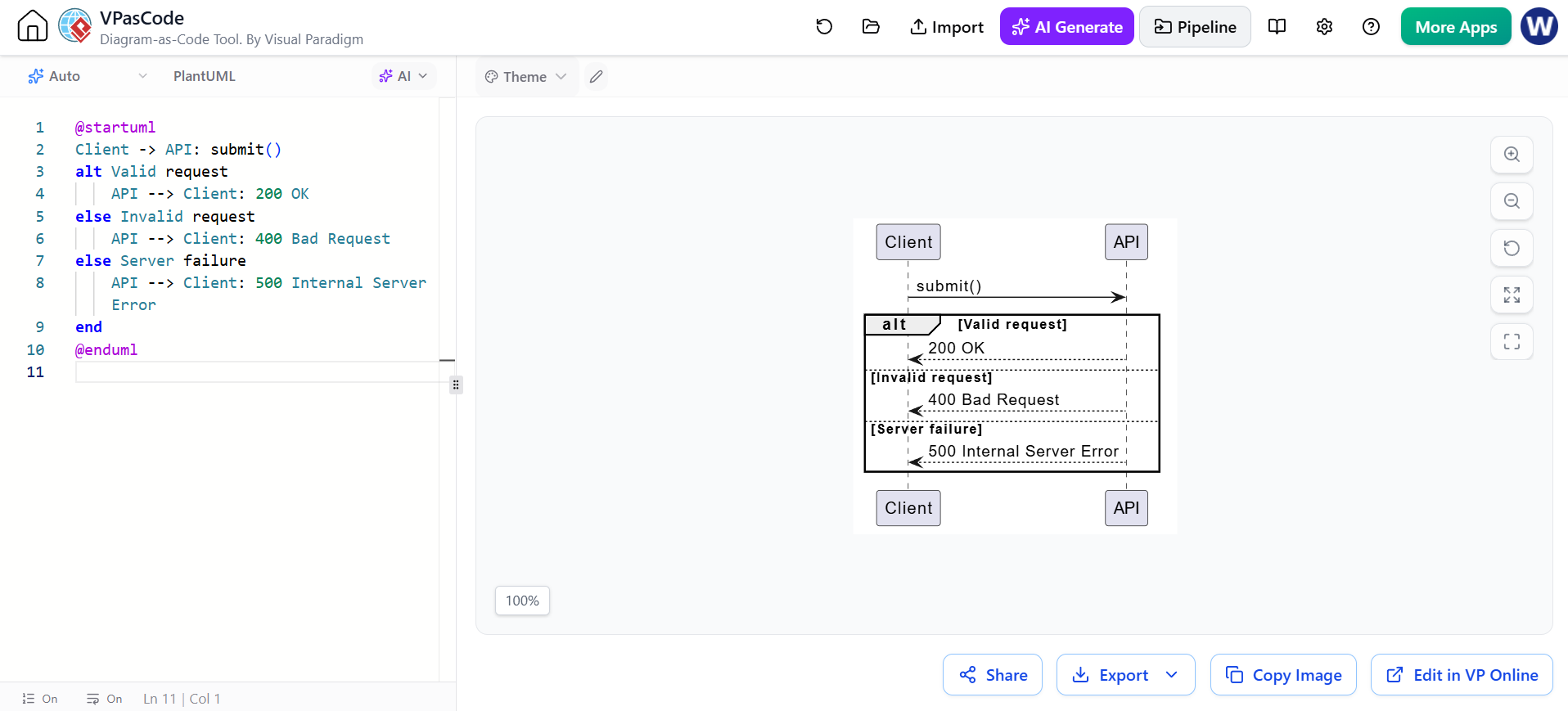
@startuml
Client -> API: submit()
alt Valid request
    API --> Client: 200 OK
else Invalid request
    API --> Client: 400 Bad Request
else Server failure
    API --> Client: 500 Internal Server Error
end
@enduml
Using par for ordinary sequential work
Use par only when paths can genuinely proceed concurrently or independently.
Confusing a return with an asynchronous event
A dashed response usually communicates a return from an earlier call. An event or notification is better represented with an asynchronous arrow such as ->>.
Overusing activations
Activations improve clarity when calls nest, but too many can make a diagram visually heavy.
Mixing scenarios
Prefer several focused diagrams over one very large diagram containing login, checkout, fulfillment, refunds, and administration.
23. PlantUML tooling
PlantUML uses a text-based, diagram-as-code approach. The source file becomes the single editable representation, which makes diagrams easy to review, store in version control, and update alongside software documentation.
A minimal file is:
@startuml
Alice -> Bob: Hello
Bob --> Alice: Hi
@enduml
Typical outputs include:
-
PNG for presentations
-
SVG for scalable documentation
-
PDF for formal specifications
-
Text or source files for version control
24. Visual Paradigm UML
Visual Paradigm provides traditional UML modeling tools for creating sequence diagrams, including a free Community Edition and online modeling options. Its UML guidance covers actors, lifelines, activations, call messages, return messages, and combined fragments.
A typical Visual Paradigm workflow is:
-
Create or open a UML project.
-
Add a Sequence Diagram.
-
Identify the actor and participating objects or services.
-
Drag participants onto the diagram.
-
Add messages between lifelines.
-
Add activation bars where participants execute operations.
-
Add combined fragments such as
alt,opt,loop, orpar. -
Add notes, guards, and return messages.
-
Arrange and format the diagram.
-
Export or include it in project documentation.
Visual Paradigm also offers a PlantUML-focused generator with a visual wizard for defining participants, messages, notes, and logical fragments, with live output and export options.
When to use Visual Paradigm’s visual editor
Use the visual UML editor when:
-
Analysts or stakeholders prefer drag-and-drop modeling
-
You need a broader UML model repository
-
You want to connect diagrams with requirements or other model elements
-
You are teaching UML notation
-
You need a diagramming workflow accessible to non-programmers
When to use PlantUML
Use PlantUML when:
-
Diagrams should live in Git
-
You want code review for diagrams
-
You need repeatable rendering
-
Documentation is generated automatically
-
The diagram changes frequently with source code
-
You prefer concise textual definitions
A practical hybrid workflow
A team can use both approaches:
-
Sketch the scenario visually in Visual Paradigm.
-
Validate actors, responsibilities, and branches with stakeholders.
-
Recreate the stable design in PlantUML.
-
Store the
.pumlfile with the project documentation. -
Render SVG or PNG files automatically in the documentation pipeline.
-
Keep Visual Paradigm as the broader UML model repository when traceability is needed.
25. Compact PlantUML reference
@startuml
title Sequence Diagram Reference

actor Actor
participant Participant
boundary Boundary
control Control
entity Entity
database Database
queue Queue

Actor -> Participant: synchronous call()
Participant --> Actor: return value
Participant ->> Queue: asynchronous event
Participant -> Participant: self-call()

activate Participant
deactivate Participant

create Entity
Participant -> Entity: created
destroy Entity

note right of Participant
  Annotation
end note

alt condition
    Participant -> Control: path A
else other condition
    Participant -> Control: path B
end

opt optional condition
    Control -> Entity: optional operation
end

loop repetition
    Control -> Database: repeated query
end

par parallel path A
    Control -> Queue: publish event
else parallel path B
    Control -> Entity: update state
end

ref over Actor, Participant
  Reusable interaction
end ref

autonumber
@enduml
The essential mental model is:
Participants are the columns, messages are the interactions, top-to-bottom order is time order, activation bars show execution, and combined fragments show control flow.
![How to Model Constraints in UML? [With Examples]](https://www.archimetric.com/wp-content/uploads/2026/04/uml-constraint-example.png "How to Model Constraints in UML? [With Examples]")


 English
 Arabic
 Chinese (Simplified)
 Dutch
Dutch French
 German
 Italian
 Japanese
 Korean
 Portuguese
 Russian
 Spanish