


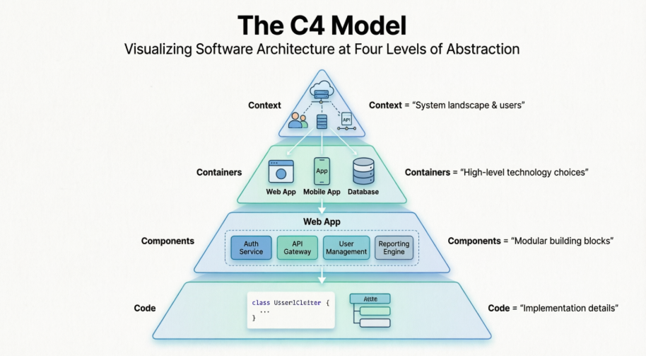
C4 modeling is a lightweight way to describe software architecture at different levels of detail. It is especially useful in Agile Enterprise Architecture because teams can create just enough documentation to support a decision, then evolve the diagrams as the solution changes.
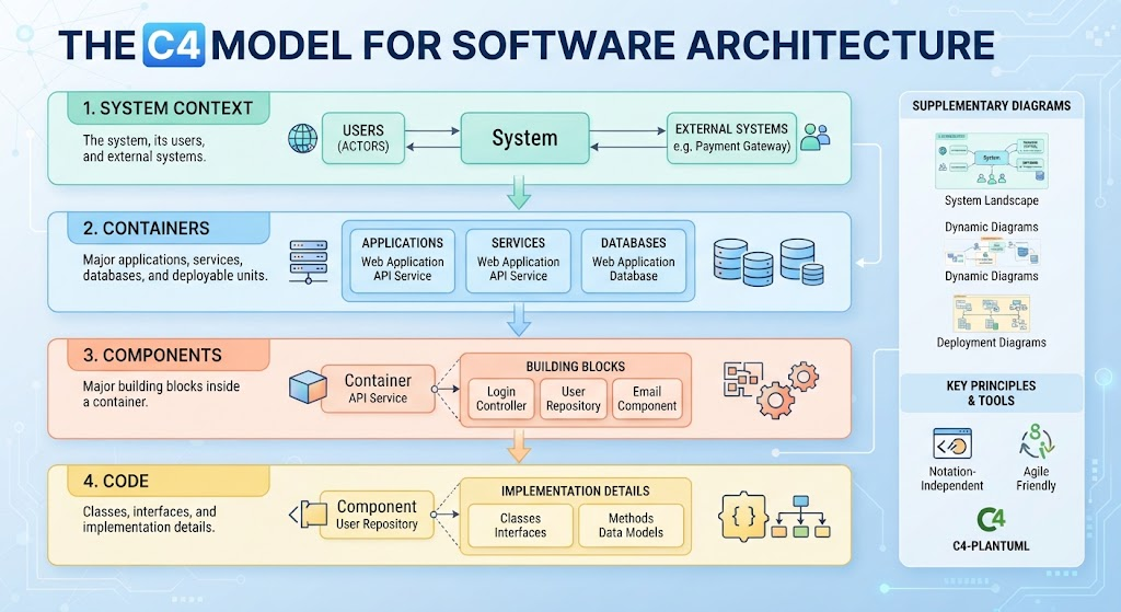
C4 uses four hierarchical levels:
-
System context — the system, its users, and external systems.
-
Containers — the major applications, services, databases, and other deployable units inside the system.
-
Components — the major building blocks inside a container.
-
Code — classes, interfaces, and implementation details.
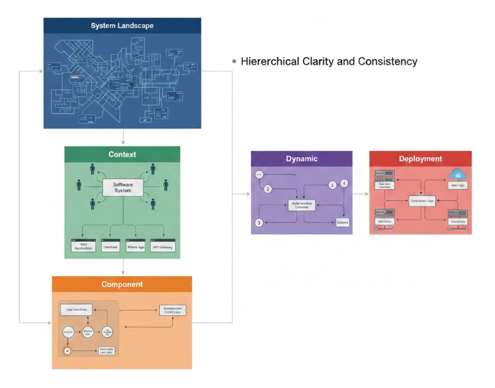
C4 also supports supplementary diagrams such as system landscapes, dynamic diagrams, and deployment diagrams. The method is notation- and tool-independent; C4-PlantUML provides a text-based way to create the diagrams.
1. Why use C4 in Agile Enterprise Architecture?
Traditional architecture documentation often becomes outdated because it is created as a large document before implementation starts. C4 modeling supports a more incremental approach:
-
Create diagrams when an architectural decision is needed.
-
Keep diagrams close to the source code and delivery backlog.
-
Review diagrams during refinement, planning, architecture forums, and retrospectives.
-
Model only the level of detail needed by the audience.
-
Update diagrams as part of normal development work.
A useful Agile principle is:
Model the architecture that helps the team make a decision, communicate a dependency, or understand a change.
For example:
-
A product owner may need a system context diagram.
-
A delivery team may need a container diagram.
-
Developers may need a component diagram.
-
A technical specialist may need a code-level diagram.
-
Operations may need a deployment diagram.
Avoid creating all four levels for every system automatically.
2. The C4 abstraction levels
Level 1: System context
A system context diagram answers:
-
What is the system?
-
Who uses it?
-
Which external systems does it interact with?
-
What is inside and outside the system boundary?
It should be understandable to technical and nontechnical stakeholders.
Example:
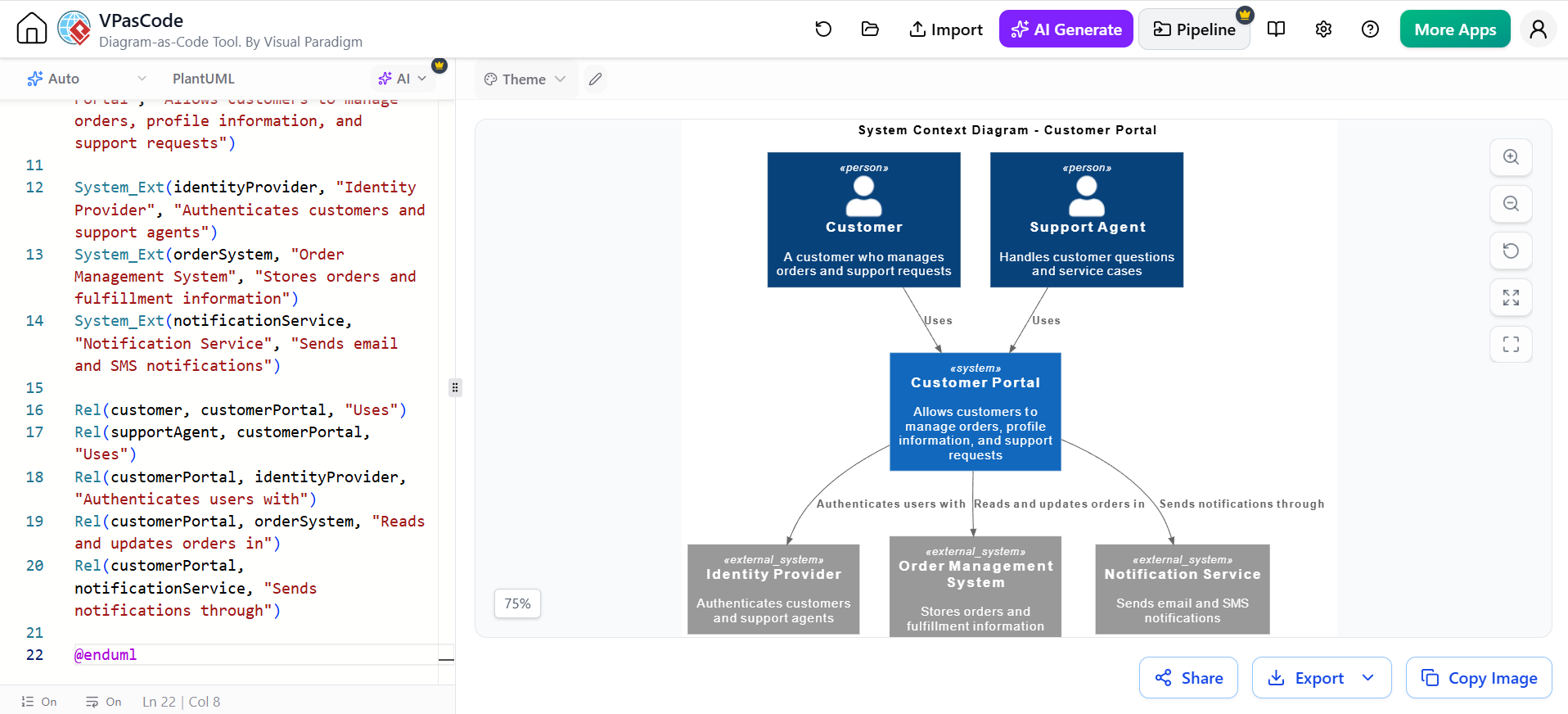
@startuml CustomerPortal_Context

!include https://raw.githubusercontent.com/plantuml-stdlib/C4-PlantUML/master/C4_Context.puml

title System Context Diagram - Customer Portal

Person(customer, "Customer", "A customer who manages orders and support requests")
Person(supportAgent, "Support Agent", "Handles customer questions and service cases")

System(customerPortal, "Customer Portal", "Allows customers to manage orders, profile information, and support requests")

System_Ext(identityProvider, "Identity Provider", "Authenticates customers and support agents")
System_Ext(orderSystem, "Order Management System", "Stores orders and fulfillment information")
System_Ext(notificationService, "Notification Service", "Sends email and SMS notifications")

Rel(customer, customerPortal, "Uses")
Rel(supportAgent, customerPortal, "Uses")
Rel(customerPortal, identityProvider, "Authenticates users with")
Rel(customerPortal, orderSystem, "Reads and updates orders in")
Rel(customerPortal, notificationService, "Sends notifications through")

@enduml
The C4_Context.puml library provides macros such as Person, System, System_Ext, and Rel. C4-PlantUML includes separate libraries for context, container, and component diagrams.
How to use this diagram in Agile work
Create or update the context diagram when:
-
A new external system is introduced.
-
A team is unsure who owns a capability.
-
A product increment changes system responsibilities.
-
You need to explain the product boundary to stakeholders.
-
A dependency creates delivery or operational risk.
Do not put internal services or databases on this diagram. Those belong in the container view.
Level 2: Container diagram
In C4, a container is a separately running or deployable unit, such as:
-
A web application
-
A mobile application
-
An API
-
A microservice
-
A serverless function
-
A database
-
A message broker
A container is not necessarily a Docker container.
A container diagram answers:
-
What are the major parts of the system?
-
What technology does each part use?
-
How do the parts communicate?
-
Which external systems do they depend on?
Example:
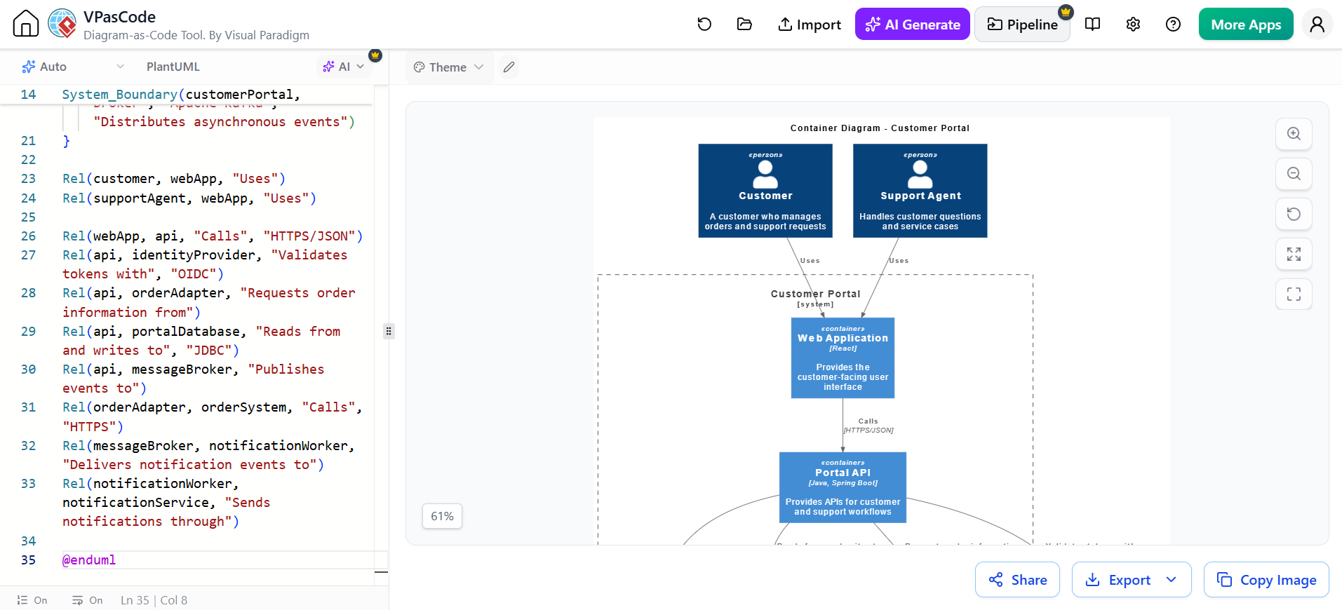
@startuml CustomerPortal_Containers

!include https://raw.githubusercontent.com/plantuml-stdlib/C4-PlantUML/master/C4_Container.puml

title Container Diagram - Customer Portal

Person(customer, "Customer", "A customer who manages orders and support requests")
Person(supportAgent, "Support Agent", "Handles customer questions and service cases")

System_Ext(identityProvider, "Identity Provider", "Authenticates users")
System_Ext(orderSystem, "Order Management System", "Stores orders and fulfillment information")
System_Ext(notificationService, "Notification Service", "Sends email and SMS notifications")

System_Boundary(customerPortal, "Customer Portal") {
    Container(webApp, "Web Application", "React", "Provides the customer-facing user interface")
    Container(api, "Portal API", "Java, Spring Boot", "Provides APIs for customer and support workflows")
    Container(orderAdapter, "Order Adapter", "Java, Spring Boot", "Translates portal requests into order-system requests")
    Container(notificationWorker, "Notification Worker", "Java, Kafka Consumer", "Processes notification events")
    ContainerDb(portalDatabase, "Portal Database", "PostgreSQL", "Stores portal-specific data such as preferences and support cases")
    Container(messageBroker, "Message Broker", "Apache Kafka", "Distributes asynchronous events")
}

Rel(customer, webApp, "Uses")
Rel(supportAgent, webApp, "Uses")

Rel(webApp, api, "Calls", "HTTPS/JSON")
Rel(api, identityProvider, "Validates tokens with", "OIDC")
Rel(api, orderAdapter, "Requests order information from")
Rel(api, portalDatabase, "Reads from and writes to", "JDBC")
Rel(api, messageBroker, "Publishes events to")
Rel(orderAdapter, orderSystem, "Calls", "HTTPS")
Rel(messageBroker, notificationWorker, "Delivers notification events to")
Rel(notificationWorker, notificationService, "Sends notifications through")

@enduml
The repository documents macros including Container, ContainerDb, System_Boundary, Boundary, and Rel.
Agile uses for a container diagram
A container diagram is useful during:
-
Solution shaping
-
Architecture runway planning
-
Nonfunctional requirement analysis
-
Team boundary discussions
-
API and integration design
-
Technology selection
-
Risk identification
-
Dependency mapping
For example, a team planning a “customer notification” feature can use the diagram to identify that the change affects:
-
The Portal API
-
The message broker
-
The notification worker
-
The external notification service
-
Monitoring and operational ownership
Level 3: Component diagram
A component diagram zooms into one container. It shows the major logical building blocks inside that container.
Use it when:
-
The container is large or complex.
-
Several teams work on the same service.
-
A new capability requires internal design.
-
Developers need to discuss responsibilities and dependencies.
-
A refactoring decision needs to be communicated.
Example for the Portal API:
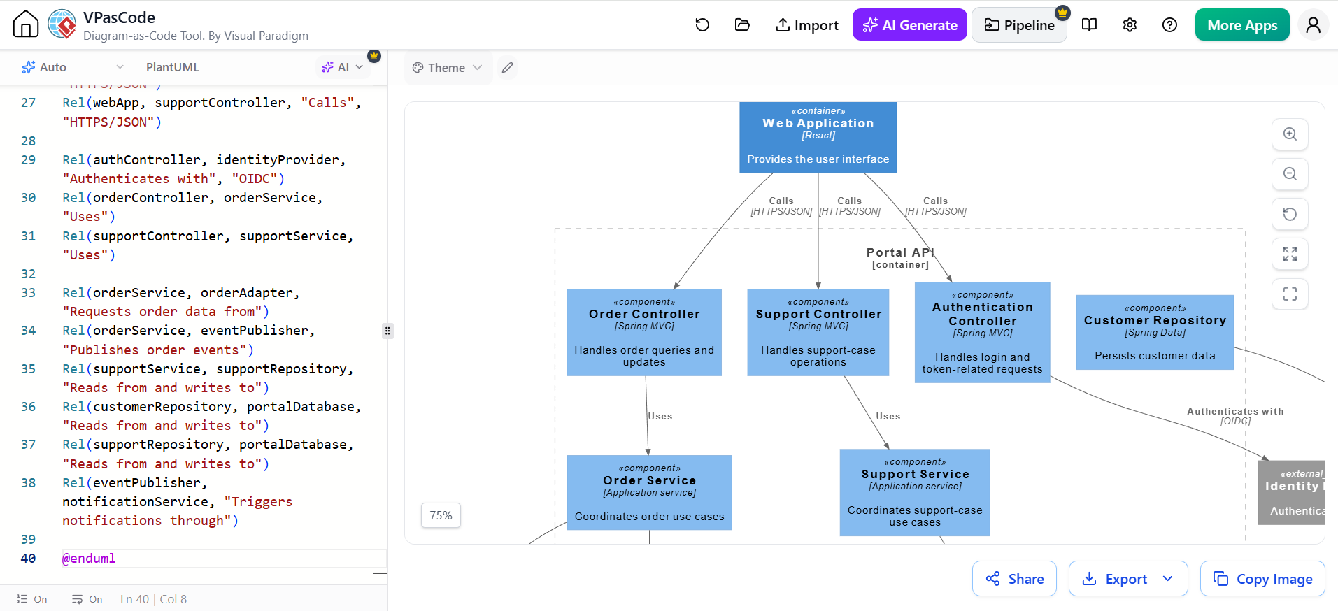
@startuml PortalApi_Components

!include https://raw.githubusercontent.com/plantuml-stdlib/C4-PlantUML/master/C4_Component.puml

title Component Diagram - Portal API

Container(webApp, "Web Application", "React", "Provides the user interface")
Container_Ext(orderAdapter, "Order Adapter", "Java, Spring Boot", "Integrates with the order system")
ContainerDb(portalDatabase, "Portal Database", "PostgreSQL", "Stores portal data")

System_Ext(identityProvider, "Identity Provider", "Authenticates users")
System_Ext(notificationService, "Notification Service", "Sends email and SMS notifications")

Container_Boundary(api, "Portal API") {
    Component(authController, "Authentication Controller", "Spring MVC", "Handles login and token-related requests")
    Component(orderController, "Order Controller", "Spring MVC", "Handles order queries and updates")
    Component(supportController, "Support Controller", "Spring MVC", "Handles support-case operations")
    Component(orderService, "Order Service", "Application service", "Coordinates order use cases")
    Component(supportService, "Support Service", "Application service", "Coordinates support-case use cases")
    Component(customerRepository, "Customer Repository", "Spring Data", "Persists customer data")
    Component(supportRepository, "Support Repository", "Spring Data", "Persists support cases")
    Component(eventPublisher, "Event Publisher", "Kafka Producer", "Publishes business events")
}

Rel(webApp, authController, "Calls", "HTTPS/JSON")
Rel(webApp, orderController, "Calls", "HTTPS/JSON")
Rel(webApp, supportController, "Calls", "HTTPS/JSON")

Rel(authController, identityProvider, "Authenticates with", "OIDC")
Rel(orderController, orderService, "Uses")
Rel(supportController, supportService, "Uses")

Rel(orderService, orderAdapter, "Requests order data from")
Rel(orderService, eventPublisher, "Publishes order events")
Rel(supportService, supportRepository, "Reads from and writes to")
Rel(customerRepository, portalDatabase, "Reads from and writes to")
Rel(supportRepository, portalDatabase, "Reads from and writes to")
Rel(eventPublisher, notificationService, "Triggers notifications through")

@enduml
C4-PlantUML uses C4_Component.puml for this level and provides macros such as Component, ComponentDb, and Container_Boundary.
Do not create component diagrams for every service by default. Create one when the internal structure is important to a current delivery decision.
Level 4: Code diagram
The code level describes implementation details such as:
-
Classes
-
Interfaces
-
Modules
-
Methods
-
Relationships
-
Data structures
For most Agile Enterprise Architecture work, manually maintaining detailed code diagrams is unnecessary. Source code, IDE tools, generated documentation, and tests usually provide better detail.
Use a code diagram when:
-
Explaining a complex framework or library.
-
Onboarding developers to a difficult area.
-
Documenting a critical domain model.
-
Planning a significant refactoring.
-
Communicating a reusable design pattern.
The key rule is to stop zooming when the diagram no longer improves communication.
3. Supporting diagrams
System landscape diagram
A system landscape shows several systems in an enterprise or business domain.
It helps answer:
-
Which systems support a business capability?
-
Where are the main integration points?
-
Which systems are candidates for replacement?
-
Which teams or business units own the systems?
Example:
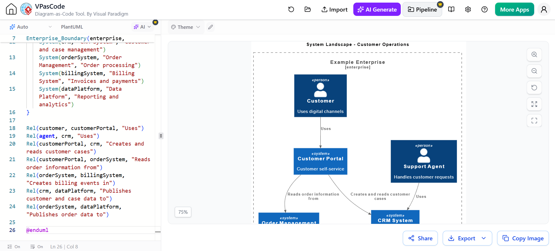
@startuml Enterprise_Landscape

!include https://raw.githubusercontent.com/plantuml-stdlib/C4-PlantUML/master/C4_Context.puml

title System Landscape - Customer Operations

Enterprise_Boundary(enterprise, "Example Enterprise") {
    Person(customer, "Customer", "Uses digital channels")
    Person(agent, "Support Agent", "Handles customer requests")

    System(customerPortal, "Customer Portal", "Customer self-service")
    System(crm, "CRM System", "Customer and case management")
    System(orderSystem, "Order Management", "Order processing")
    System(billingSystem, "Billing System", "Invoices and payments")
    System(dataPlatform, "Data Platform", "Reporting and analytics")
}

Rel(customer, customerPortal, "Uses")
Rel(agent, crm, "Uses")
Rel(customerPortal, crm, "Creates and reads customer cases")
Rel(customerPortal, orderSystem, "Reads order information from")
Rel(orderSystem, billingSystem, "Creates billing events in")
Rel(crm, dataPlatform, "Publishes customer and case data to")
Rel(orderSystem, dataPlatform, "Publishes order data to")

@enduml
Enterprise_Boundary and related boundary macros are useful for showing groups of systems in a larger landscape.
Dynamic diagram
A dynamic diagram shows how elements collaborate during a particular scenario or use case.
Example: submitting a support request.
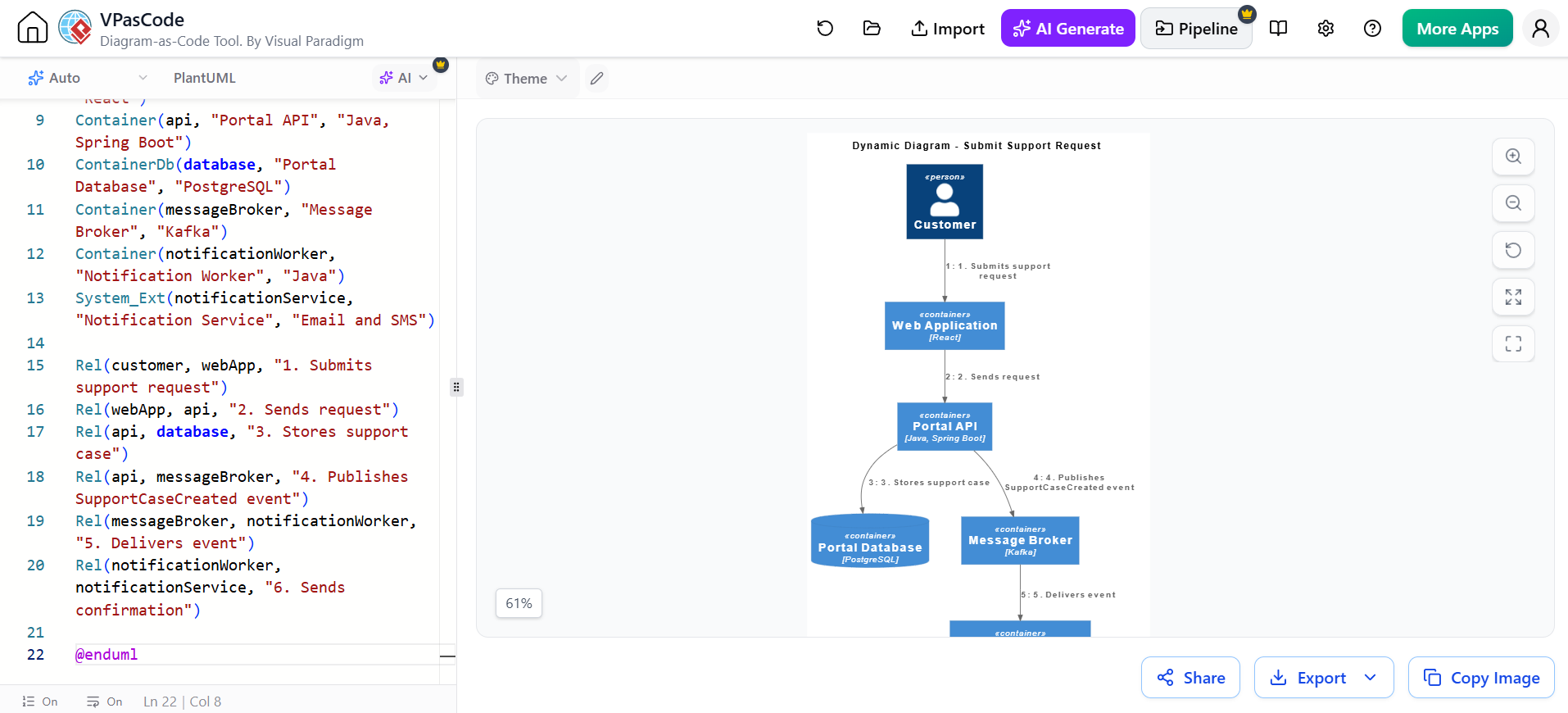
@startuml SubmitSupportRequest_Dynamic

!include https://raw.githubusercontent.com/plantuml-stdlib/C4-PlantUML/master/C4_Dynamic.puml

title Dynamic Diagram - Submit Support Request

Person(customer, "Customer")
Container(webApp, "Web Application", "React")
Container(api, "Portal API", "Java, Spring Boot")
ContainerDb(database, "Portal Database", "PostgreSQL")
Container(messageBroker, "Message Broker", "Kafka")
Container(notificationWorker, "Notification Worker", "Java")
System_Ext(notificationService, "Notification Service", "Email and SMS")

Rel(customer, webApp, "1. Submits support request")
Rel(webApp, api, "2. Sends request")
Rel(api, database, "3. Stores support case")
Rel(api, messageBroker, "4. Publishes SupportCaseCreated event")
Rel(messageBroker, notificationWorker, "5. Delivers event")
Rel(notificationWorker, notificationService, "6. Sends confirmation")

@enduml
The exact dynamic-diagram macros can vary with the C4-PlantUML version. Check the repository’s current samples when using advanced dynamic or sequence features.
Deployment diagram
A deployment diagram shows where containers run.
Example:
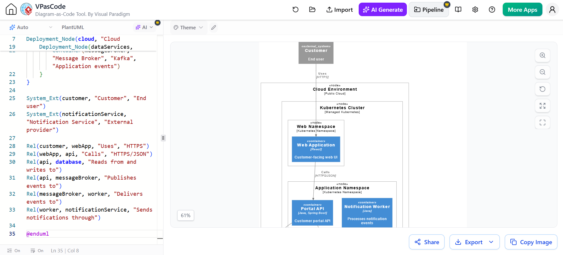
@startuml CustomerPortal_Deployment

!include https://raw.githubusercontent.com/plantuml-stdlib/C4-PlantUML/master/C4_Deployment.puml

title Deployment Diagram - Production

Deployment_Node(cloud, "Cloud Environment", "Public Cloud") {
    Deployment_Node(kubernetes, "Kubernetes Cluster", "Managed Kubernetes") {
        Deployment_Node(webNode, "Web Namespace", "Kubernetes Namespace") {
            Container(webApp, "Web Application", "React", "Customer-facing web UI")
        }

        Deployment_Node(apiNode, "Application Namespace", "Kubernetes Namespace") {
            Container(api, "Portal API", "Java, Spring Boot", "Customer portal API")
            Container(worker, "Notification Worker", "Java", "Processes notification events")
        }
    }

    Deployment_Node(dataServices, "Managed Data Services", "Cloud services") {
        ContainerDb(database, "Portal Database", "PostgreSQL", "Portal data")
        Container(messageBroker, "Message Broker", "Kafka", "Application events")
    }
}

System_Ext(customer, "Customer", "End user")
System_Ext(notificationService, "Notification Service", "External provider")

Rel(customer, webApp, "Uses", "HTTPS")
Rel(webApp, api, "Calls", "HTTPS/JSON")
Rel(api, database, "Reads from and writes to")
Rel(api, messageBroker, "Publishes events to")
Rel(messageBroker, worker, "Delivers events to")
Rel(worker, notificationService, "Sends notifications through")

@enduml
Deployment diagrams are valuable for discussions about:
-
Availability
-
Network zones
-
Scaling
-
Disaster recovery
-
Security boundaries
-
Operational ownership
-
Environment differences
4. Installing and using C4-PlantUML
C4-PlantUML is a collection of PlantUML macros, stereotypes, and supporting features for creating C4 diagrams. The project includes examples, layout options, and editor snippets.
You have two main inclusion options.
Option A: Include the current repository version
!include https://raw.githubusercontent.com/plantuml-stdlib/C4-PlantUML/master/C4_Context.puml
For a container diagram:
!include https://raw.githubusercontent.com/plantuml-stdlib/C4-PlantUML/master/C4_Container.puml
For a component diagram:
!include https://raw.githubusercontent.com/plantuml-stdlib/C4-PlantUML/master/C4_Component.puml
This approach is convenient but requires network access when rendering. The project documentation shows these remote include patterns.
Option B: Use local or standard-library files
For more repeatable builds, use a local copy or the PlantUML standard library:
Or:
The repository also documents downloading the files and using a local RELATIVE_INCLUDE configuration so diagrams can be rendered without internet connectivity.
A practical team policy is:
-
Use a pinned local or standard-library version for CI and published architecture documentation.
-
Use a controlled update process when upgrading the C4-PlantUML library.
-
Avoid silently changing diagram output because an external include changed.
5. Common C4-PlantUML elements
| Purpose | Macro example |
|---|---|
| Internal person | Person(customer, "Customer", "Description") |
| External person | Person_Ext(partner, "Partner", "Description") |
| Internal system | System(portal, "Customer Portal", "Description") |
| External system | System_Ext(crm, "CRM System", "Description") |
| Application container | Container(api, "Portal API", "Java", "Description") |
| Database container | ContainerDb(db, "Database", "PostgreSQL", "Description") |
| Internal boundary | System_Boundary(system, "System Name") { ... } |
| Container boundary | Container_Boundary(api, "API") { ... } |
| Relationship | Rel(a, b, "Uses", "HTTPS") |
| Directional relationship | Rel_R(a, b, "Uses") |
| Component | Component(service, "Order Service", "Java", "Description") |
Relationship labels should describe meaningful behavior, not merely say “connects to.”
Prefer:
Rel(webApp, api, "Retrieves customer orders", "HTTPS/JSON")
Over:
The more useful relationship communicates:
-
The purpose of the interaction
-
The protocol or technology
-
Sometimes the direction or data being exchanged
6. A practical Agile workflow
Step 1: Establish the system boundary
Start with a short workshop involving:
-
Product owner
-
Developers
-
Architect or technical lead
-
Operations representative
-
Relevant external-system owners
Identify:
-
Users
-
Business systems
-
External providers
-
Ownership boundaries
-
Key business responsibilities
Capture the result as a system context diagram.
Step 2: Identify containers
Ask:
-
What runs independently?
-
What is deployed independently?
-
What stores data?
-
What communicates asynchronously?
-
What is owned by another system or team?
Create a container diagram only after the system boundary is understood.
Step 3: Add architectural decisions
For each significant relationship, record decisions such as:
-
Synchronous versus asynchronous integration
-
API style
-
Data ownership
-
Authentication mechanism
-
Failure handling
-
Availability requirements
-
Monitoring responsibility
A diagram should lead to useful conversations, not replace them.
Step 4: Create focused component diagrams
Create a component diagram for a container when a current backlog item needs internal design clarification.
For example:
-
“Add customer support cases.”
-
“Split order processing from the portal API.”
-
“Introduce an event-driven notification flow.”
-
“Replace direct database access with a repository boundary.”
Step 5: Validate with delivery teams
Review the diagrams with the people who build and operate the system. Ask:
-
Does this reflect the actual architecture?
-
Are any boundaries misleading?
-
Are relationships missing?
-
Is a container being confused with a component?
-
Does the diagram reveal an unowned dependency?
-
Will this remain useful after the next increment?
Step 6: Store diagrams with the work
A typical repository layout might be:
architecture/
├── context/
│   └── customer-portal-context.puml
├── containers/
│   └── customer-portal-containers.puml
├── components/
│   └── portal-api-components.puml
├── dynamic/
│   └── submit-support-request.puml
├── deployment/
│   └── customer-portal-production.puml
└── decisions/
    ├── adr-001-api-boundary.md
    └── adr-002-notification-events.md
Keep diagrams versioned with the software whenever possible.
7. Definition of done for an architecture diagram
A diagram is ready when:
-
Its purpose and audience are clear.
-
The scope is stated in the title.
-
The system boundary is unambiguous.
-
Elements have meaningful names.
-
Relationships describe responsibilities or interactions.
-
Technologies are shown where they matter.
-
External systems are distinguished from internal elements.
-
The diagram renders successfully.
-
The delivery team has reviewed it.
-
It is stored in a version-controlled location.
-
It has an owner or review responsibility.
For Agile work, “complete” does not mean “exhaustive.” It means useful, understandable, and sufficiently accurate for the decision at hand.
8. Common beginner mistakes
Modeling infrastructure too early
A context diagram does not need Kubernetes nodes, database tables, or class names. Start with the appropriate abstraction level.
Treating every process as a container
A container should normally represent a major application, service, data store, or independently running unit. A business process inside an API is usually a component or a responsibility, not a container.
Mixing abstraction levels
Avoid placing a class, a database, a business capability, and an external enterprise system on the same diagram unless the purpose is very specific.
Showing technology without responsibility
“Java service” is less useful than:
Order Service — Java/Spring Boot — coordinates order retrieval and order updates.
Using vague relationship labels
Replace “uses” with a meaningful action where possible:
-
“Authenticates with”
-
“Publishes order events to”
-
“Reads customer data from”
-
“Submits support cases to”
-
“Receives payment status from”
Creating diagrams that nobody maintains
An inaccurate architecture diagram is often worse than no diagram. Include diagram updates in the definition of done for architecture-affecting work.
Overusing layout commands
Manual layout can improve readability, but too many positioning commands make diagrams fragile. C4-PlantUML provides layout options such as top-down, left-right, legend, and sketch-style layouts.
Example:
LAYOUT_LEFT_RIGHT()
LAYOUT_WITH_LEGEND()
Use layout commands to improve readability, not to encode architectural meaning.
9. A lightweight governance model
For an Agile EA initiative, use lightweight governance:
-
Team level: teams own diagrams for the systems they build.
-
Architecture level: an architecture group reviews cross-team boundaries and significant dependencies.
-
Product level: product owners validate business scope and terminology.
-
Operations level: platform or operations teams validate deployment and support responsibilities.
-
Portfolio level: enterprise architects use system landscape views to identify duplication, strategic dependencies, and modernization candidates.
A useful review cadence is:
-
Context diagrams: review when system scope or ownership changes.
-
Container diagrams: review during major features and architectural changes.
-
Component diagrams: review during implementation of complex capabilities.
-
Deployment diagrams: review when environments, hosting, or operational architecture changes.
10. Recommended starting set
For a beginner’s first Agile EA project, create these three diagrams:
-
System context diagram
Shows users, the system, and external dependencies. -
Container diagram
Shows the system’s major applications, services, databases, and message flows. -
One focused component diagram
Shows the internals of the container currently undergoing the most change.
Add dynamic and deployment diagrams only when they answer a specific question.
The main goal is not to produce a large collection of attractive diagrams. It is to create a shared, versioned architectural vocabulary that helps teams deliver change with fewer misunderstandings.
Visual Paradigm C4 Tool: Reference Article List
Based on the search results, here is a curated list of English articles and posts about Visual Paradigm’s C4 modeling capabilities and related AI-powered tools.
-
From Big Picture to Code: A Beginner’s Guide to Visualizing Software Architecture with the C4 Model: Step-by-step beginner tutorial covering all four C4 levels with practical PayQuick payment platform examples and PlantUML code snippets.
-
Mastering the AI + C4 Model + Diagram as Code: A Hybrid Approach to Software Architecture Diagrams: Explains why Visual Paradigm remains essential for professional architects and presents a hybrid workflow combining AI, C4, and diagram-as-code.
-
The Ultimate Guide to C4-PlantUML Studio: Revolutionizing Software Architecture Design: Comprehensive guide covering AI-powered generation, step-by-step workflows, real-world use cases, and why Visual Paradigm leads the market.
-
Mastering Software Architecture with the C4 Model and Visual Paradigm: Evaluation of Visual Paradigm’s C4 ecosystem including hierarchical navigation, living documentation integration, and practical workflow for linking context to container diagrams.
-
Architecting Smart Infrastructure: A C4 Model Case Study of an EV Charging Network Using Visual Paradigm’s AI-Powered Tools: Real-world case study demonstrating AI-powered C4 generation for an EV charging network with measurable outcomes.
Related posts:
 The Comprehensive Guide to the C4 Model for Software Architecture
 Comprehensive Guide to the C4 Model for Software Architecture Documentation
![How to Model Constraints in UML? [With Examples]](https://www.archimetric.com/wp-content/uploads/2026/04/uml-constraint-example.png "How to Model Constraints in UML? [With Examples]") How to Model Constraints in UML? [With Examples]
How to Model Constraints in UML? [With Examples]
 A Practical Guide to C4 Modeling with AI-Powered Visual Paradigm Tools: Architecting Scalable E-Commerce Systems

 English
 Arabic
 Chinese (Simplified)
 Dutch
Dutch French
 German
 Italian
 Japanese
 Korean
 Portuguese
 Russian
 Spanish