


A UML class diagram describes the static structure of a system. It shows the classes in a domain, their data, behavior, and relationships.
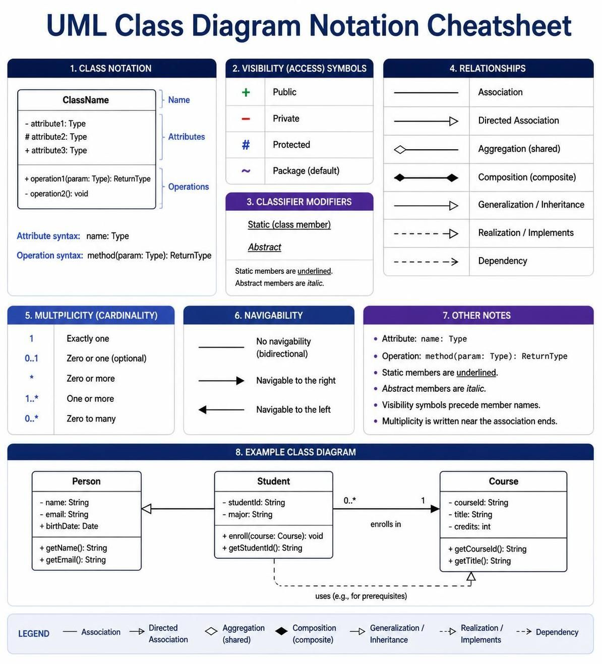
Class diagrams are useful for:
-
Modeling business domains
-
Designing object-oriented software
-
Communicating architecture
-
Reviewing responsibilities and dependencies
-
Generating code or documentation
-
Explaining an existing codebase
A good class diagram answers three questions:
-
What are the important concepts?
-
What information and behavior belong to each concept?
-
How are the concepts related?
1. The Basic Structure of a Class
A UML class is usually drawn as a rectangle divided into three sections:
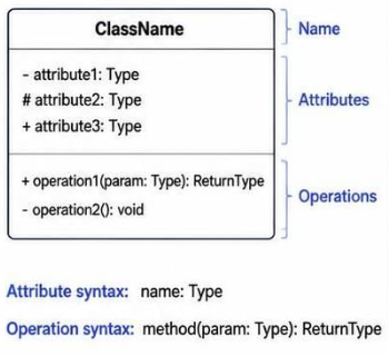
The sections are:
-
Class name
-
Attributes
-
Operations
The equivalent PlantUML code is:
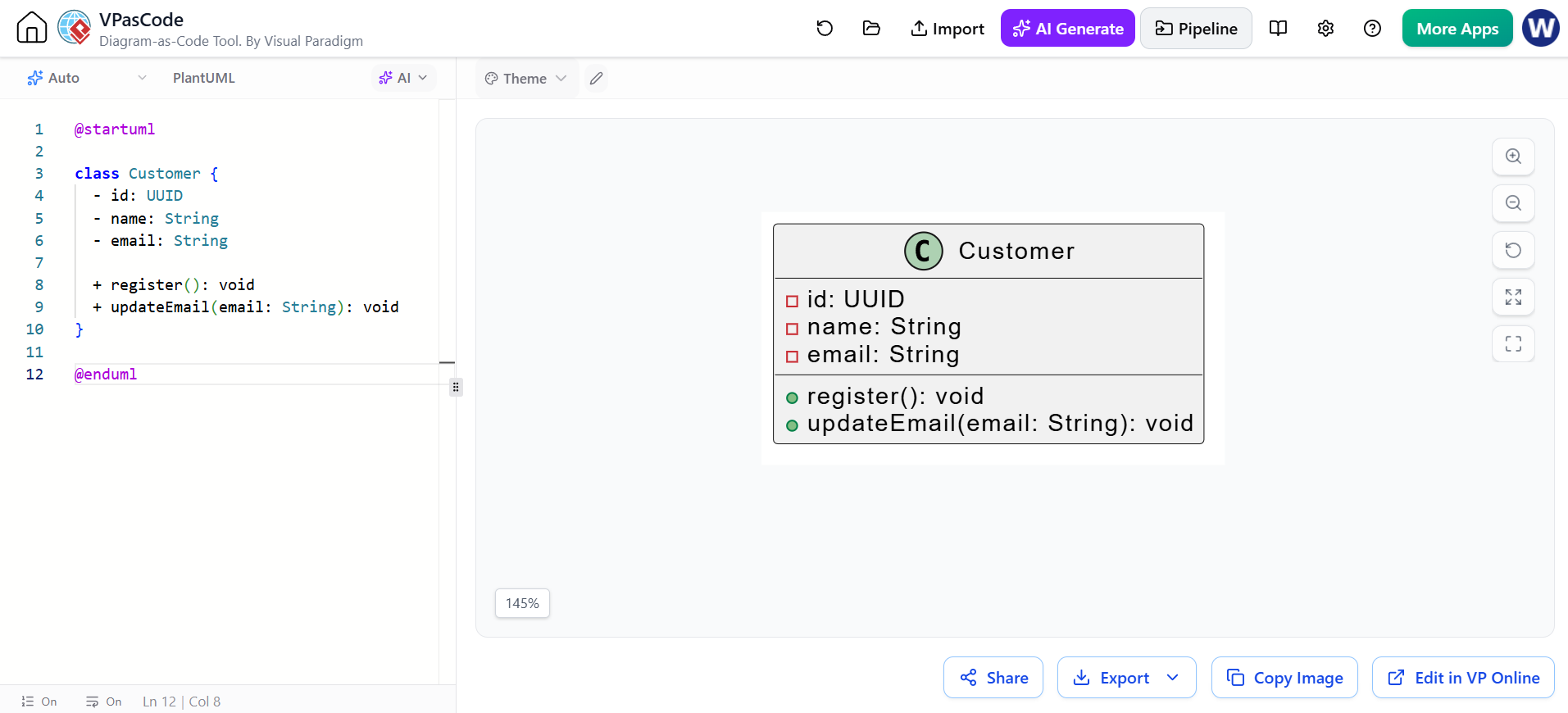
@startuml

class Customer {
  - id: UUID
  - name: String
  - email: String

  + register(): void
  + updateEmail(email: String): void
}

@enduml
Class names
Class names normally use PascalCase:
class Customer
class ShoppingCart
class PaymentService
class OrderItem
A class name should usually be a noun representing a meaningful concept.
Good examples:
Customer
Invoice
Product
Reservation
Payment
Less useful examples:
Manager
Data
SystemThing
Helper
Avoid creating classes merely because a noun appears in a requirements document. A class should have a clear responsibility or represent an important domain concept.
2. Attributes
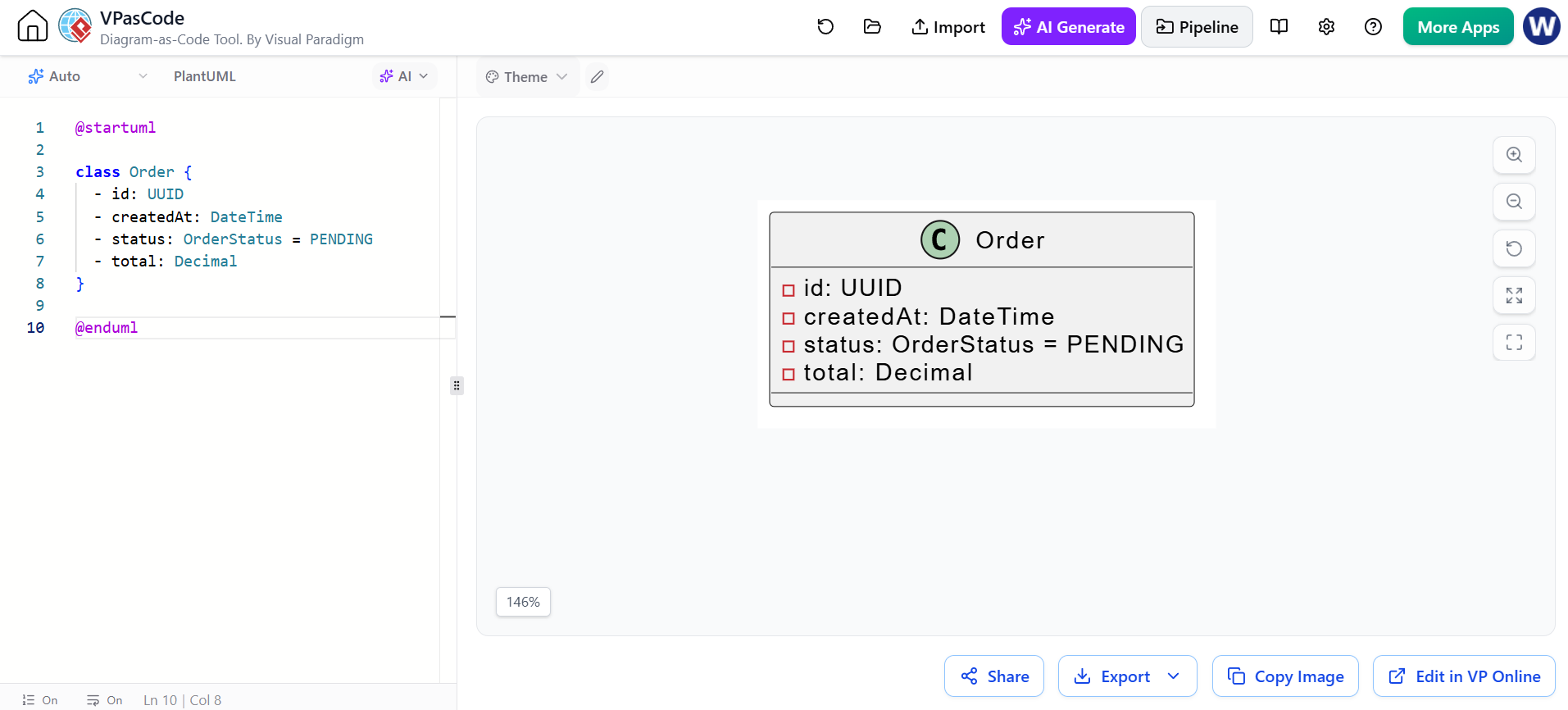
Attributes describe the state or data held by a class.
The general notation is:
visibility name: Type = defaultValue
Examples:
- id: UUID
- quantity: Integer
- createdAt: DateTime
+ status: OrderStatus = PENDING
PlantUML:
@startuml

class Order {
  - id: UUID
  - createdAt: DateTime
  - status: OrderStatus = PENDING
  - total: Decimal
}

@enduml
Common attribute types
class Product {
  - name: String
  - price: Decimal
  - quantityInStock: Integer
  - available: Boolean
  - tags: List<String>
  - dimensions: Dimensions
}
Use domain-specific types where they improve clarity:
class Customer {
  - email: EmailAddress
  - phone: PhoneNumber
  - address: PostalAddress
}
A domain type such as EmailAddress can make validation and business rules more explicit than using a plain String.
Derived attributes
A derived attribute is calculated from other information. UML commonly marks it with a slash:
class Account {
  - balance: Decimal
  / availableCredit: Decimal
}
The / indicates that availableCredit is derived rather than stored independently.
3. Operations
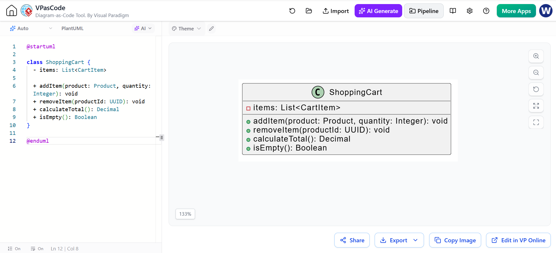
Operations describe behavior provided by a class.
The general notation is:
visibility operation(parameter: Type): ReturnType
Example:
@startuml

class ShoppingCart {
  - items: List<CartItem>

  + addItem(product: Product, quantity: Integer): void
  + removeItem(productId: UUID): void
  + calculateTotal(): Decimal
  + isEmpty(): Boolean
}

@enduml
Operations should represent meaningful behavior. Prefer:
+ approve(): void
+ calculateTotal(): Money
+ cancel(reason: String): void
over vague methods such as:
+ process(): void
+ handle(): void
+ doSomething(): void
Constructors and accessors
Getters and setters can be shown when they are architecturally relevant:
class Customer {
  - name: String

  + getName(): String
  + setName(name: String): void
}
However, adding every automatically generated getter and setter can make a diagram unnecessarily large. Include them when they help explain the public API.
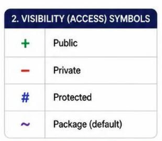
4. Visibility Symbols
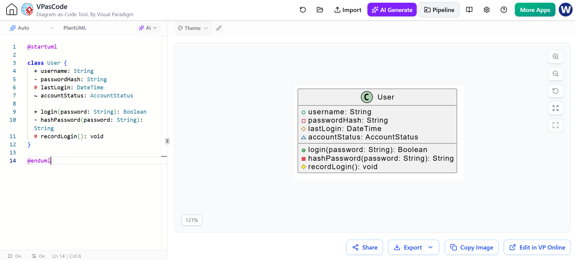
UML uses symbols to describe visibility:
| Symbol | Meaning | Typical programming equivalent |
|---|---|---|
+ |
Public | public |
- |
Private | private |
# |
Protected | protected |
~ |
Package or default visibility | package-private/internal |
PlantUML example:
@startuml

class User {
  + username: String
  - passwordHash: String
  # lastLogin: DateTime
  ~ accountStatus: AccountStatus

  + login(password: String): Boolean
  - hashPassword(password: String): String
  # recordLogin(): void
}

@enduml
Use private attributes by default unless external access is part of the design.
5. Static and Abstract Members
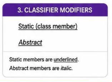
Static members
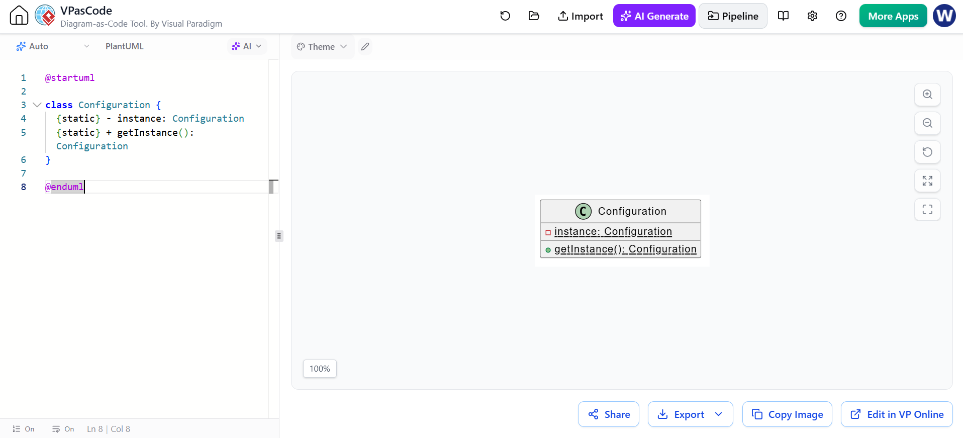
Static members belong to the class rather than to an individual object. UML commonly underlines them.
PlantUML:
@startuml

class Configuration {
  {static} - instance: Configuration
  {static} + getInstance(): Configuration
}

@enduml
Depending on the PlantUML version and rendering style, {static} communicates the intent even when underlining is not visually obvious.
Abstract classes
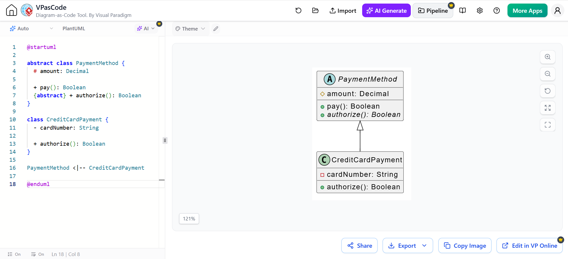
An abstract class provides common behavior but is not normally instantiated directly.
PlantUML:
@startuml

abstract class PaymentMethod {
  # amount: Decimal

  + pay(): Boolean
  {abstract} + authorize(): Boolean
}

class CreditCardPayment {
  - cardNumber: String

  + authorize(): Boolean
}

PaymentMethod <|-- CreditCardPayment

@enduml
Abstract class names are often rendered in italics or marked with the abstract keyword.
Interfaces
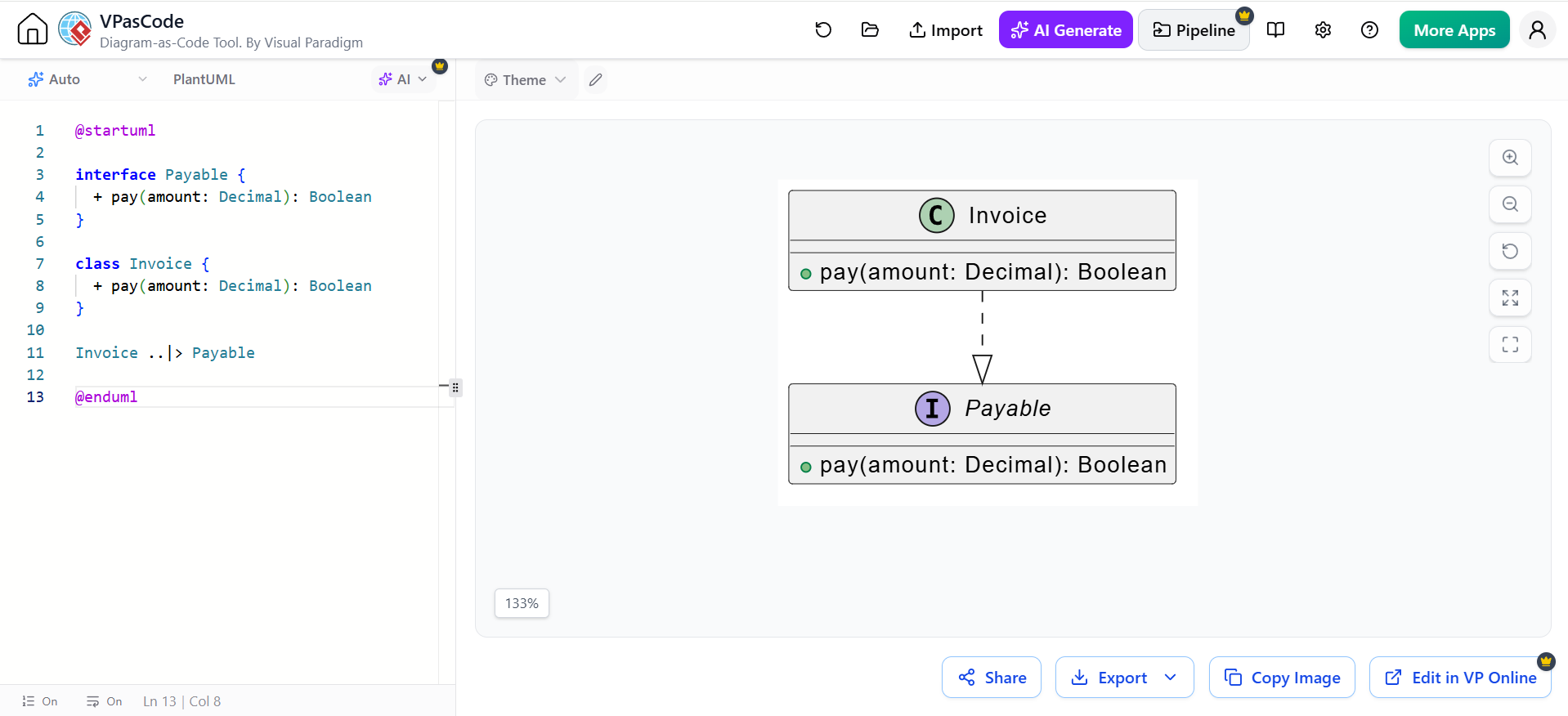
An interface specifies a contract that implementing classes must fulfill.
@startuml

interface Payable {
  + pay(amount: Decimal): Boolean
}

class Invoice {
  + pay(amount: Decimal): Boolean
}

Invoice ..|> Payable

@enduml
The ..|> relationship means that Invoice realizes or implements Payable.
6. Relationships Between Classes
Relationships are one of the most important parts of a class diagram. They explain how classes collaborate or depend on one another.
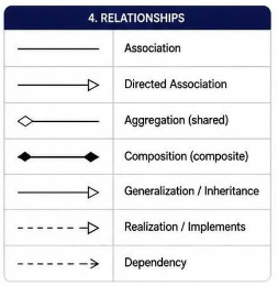
The main relationship types are:
-
Association
-
Directed association
-
Aggregation
-
Composition
-
Generalization or inheritance
-
Realization or implementation
-
Dependency
6.1 Association
An association is a structural connection between two classes.
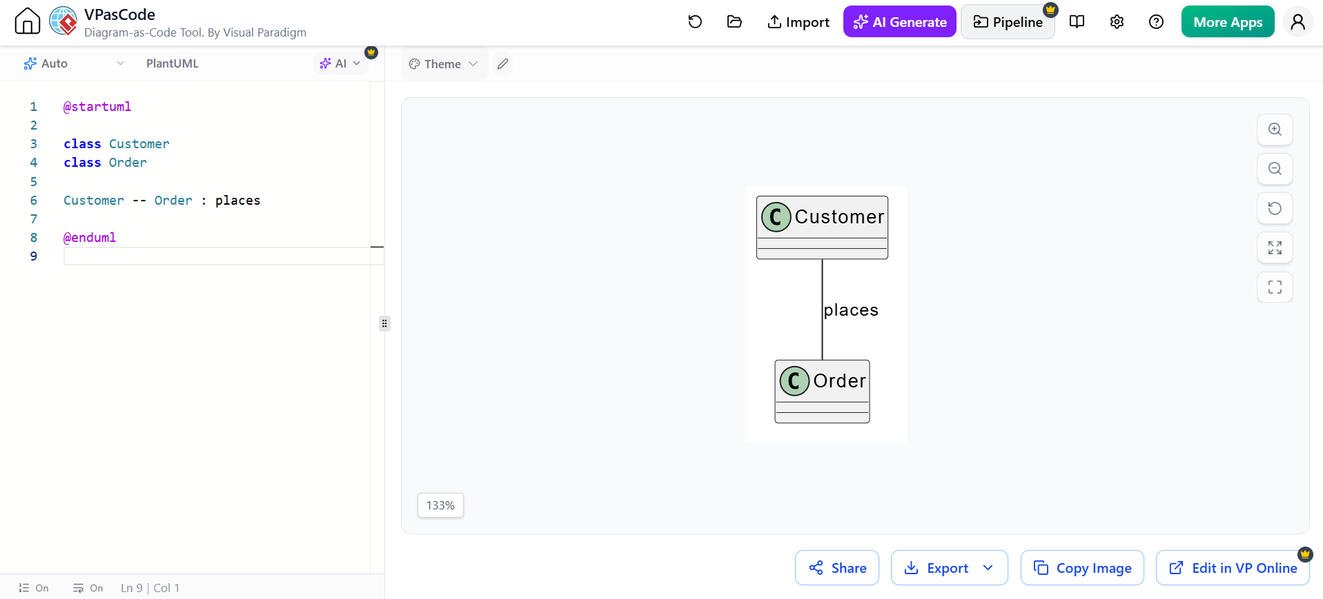
@startuml

class Customer
class Order

Customer -- Order

@enduml
This means that a Customer is associated with an Order.
Associations often have role names:
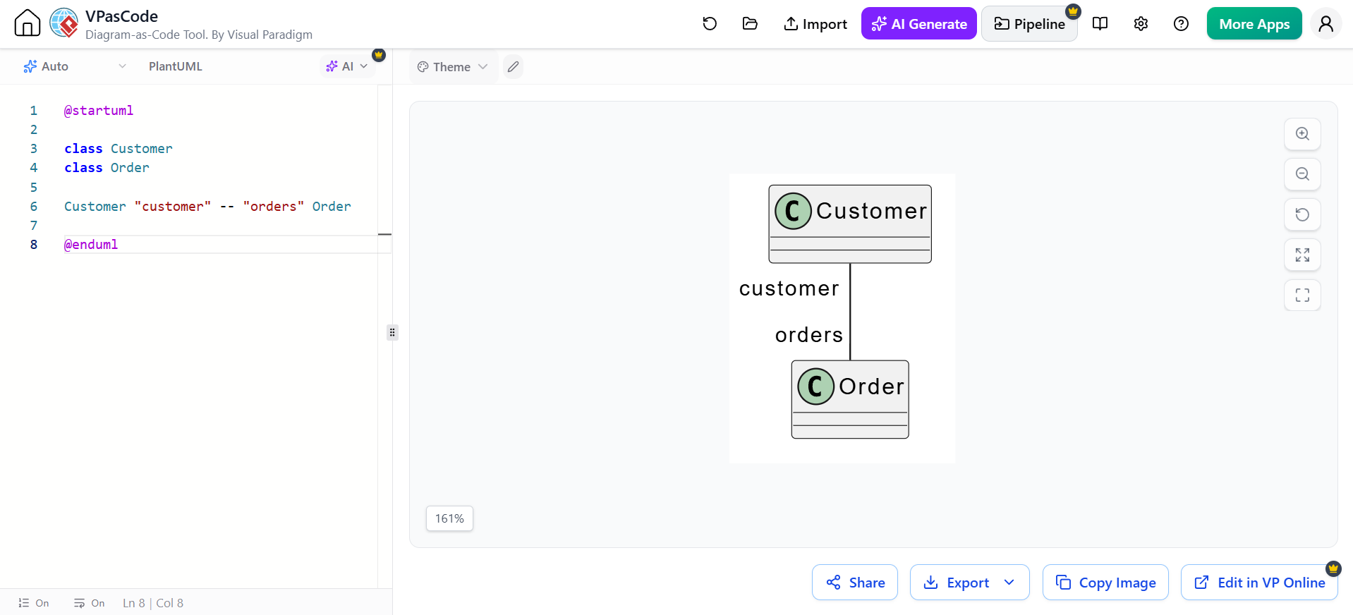
@startuml

class Customer
class Order

Customer "customer" -- "orders" Order

@enduml
The role names describe how each class participates in the relationship.
Association labels
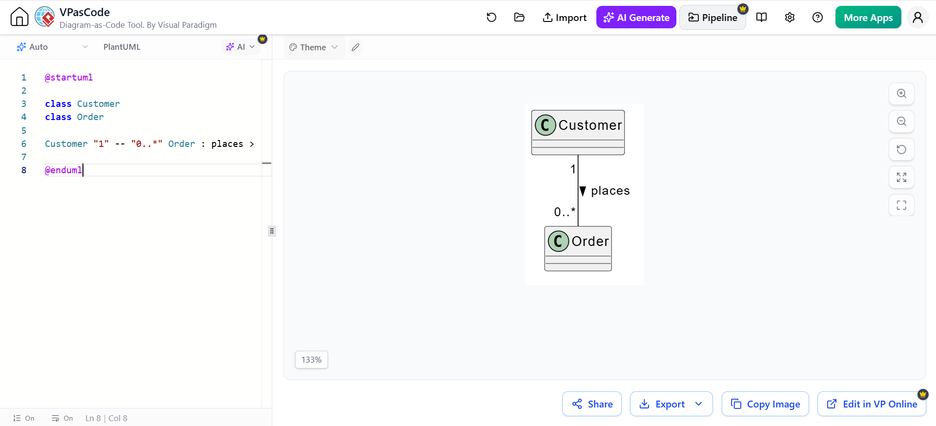
@startuml

class Customer
class Order

Customer "1" -- "0..*" Order : places >

@enduml
The label places describes the relationship semantically.
6.2 Directed Association
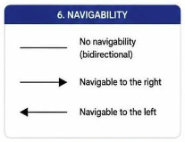
A directed association indicates navigability: one class knows about or can access the other.
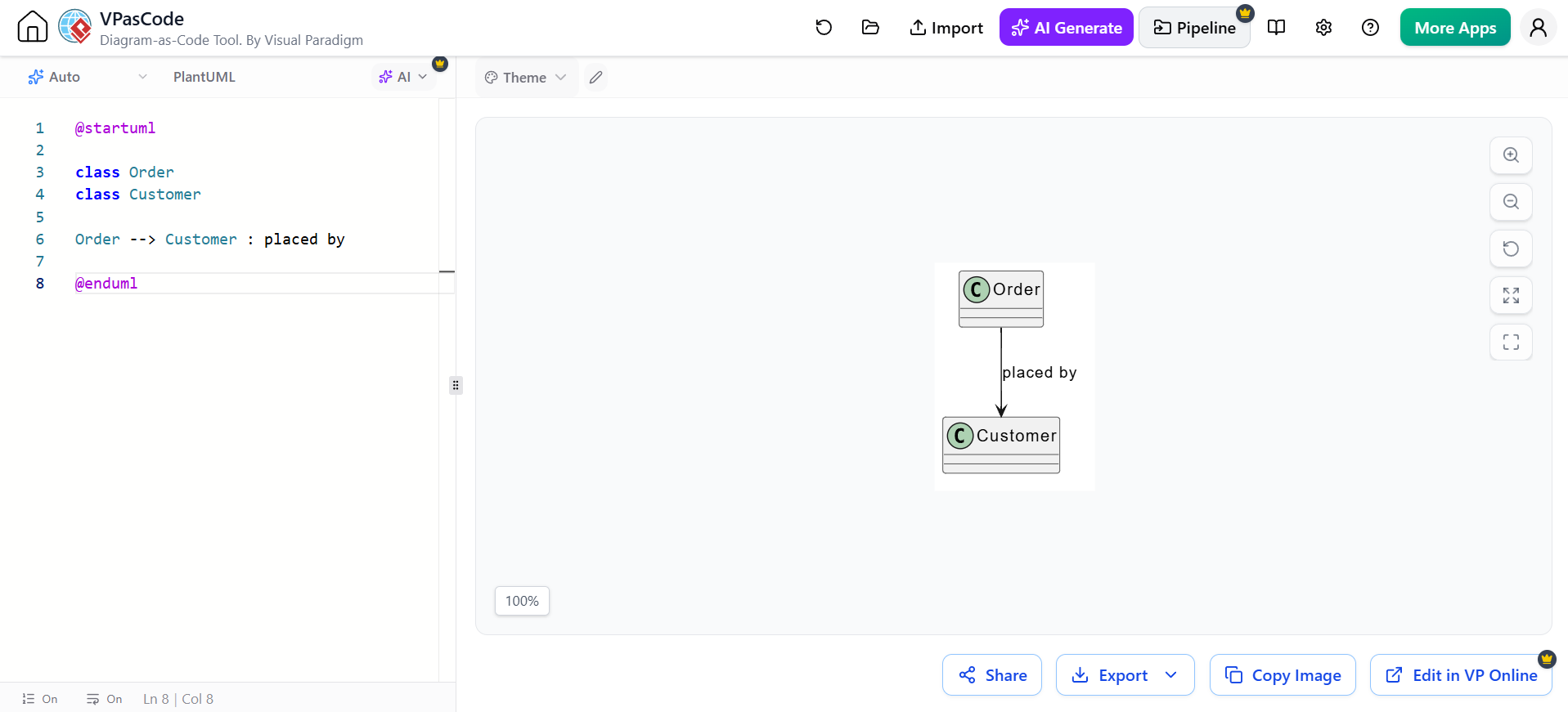
@startuml

class Order
class Customer

Order --> Customer : placed by

@enduml
This indicates that Order navigates to Customer.
In software design, direction can represent a reference:
Use directional arrows carefully. An arrow should communicate an intentional design decision, not merely improve visual appearance.
6.3 Multiplicity
Multiplicity specifies how many instances of one class may be associated with another.
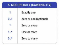
| Multiplicity | Meaning |
|---|---|
1 |
Exactly one |
0..1 |
Zero or one |
* |
Many, including zero |
0..* |
Zero or more |
1..* |
One or more |
2..5 |
Between two and five |
2, 4, 6 |
Two, four, or six |
Example:
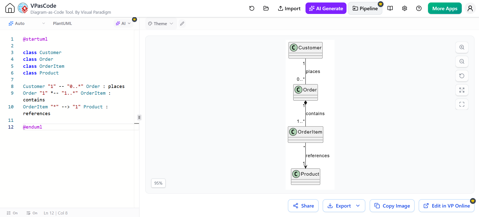
@startuml

class Customer
class Order
class OrderItem
class Product

Customer "1" -- "0..*" Order : places
Order "1" *-- "1..*" OrderItem : contains
OrderItem "*" --> "1" Product : references

@enduml
Interpretation:
-
One customer can place zero or many orders.
-
One order contains one or more order items.
-
Many order items can reference one product.
Multiplicity should be placed near the end of the relationship where it applies.
6.4 Aggregation
Aggregation represents a whole-part relationship in which the parts can exist independently of the whole.
It is shown with a hollow diamond.
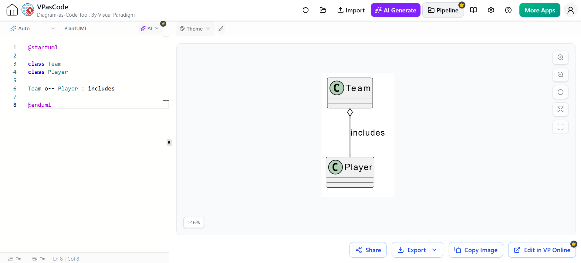
@startuml

class Team
class Player

Team o-- Player : includes

@enduml
A player can exist independently of a team, so deleting the team does not necessarily delete the players.
Another example:
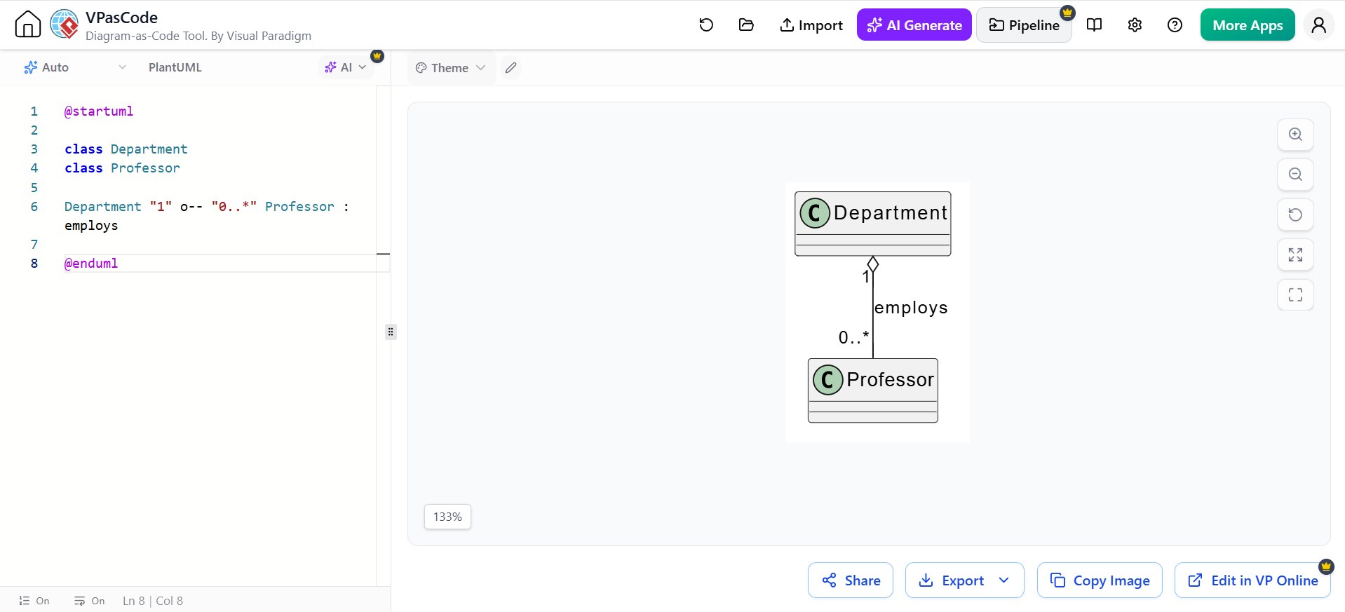
@startuml

class Department
class Professor

Department "1" o-- "0..*" Professor : employs

@enduml
Aggregation is often overused. If there is no meaningful whole-part relationship, use an ordinary association instead.
6.5 Composition
Composition represents strong ownership. The part normally cannot exist independently of the whole.
It is shown with a filled diamond.
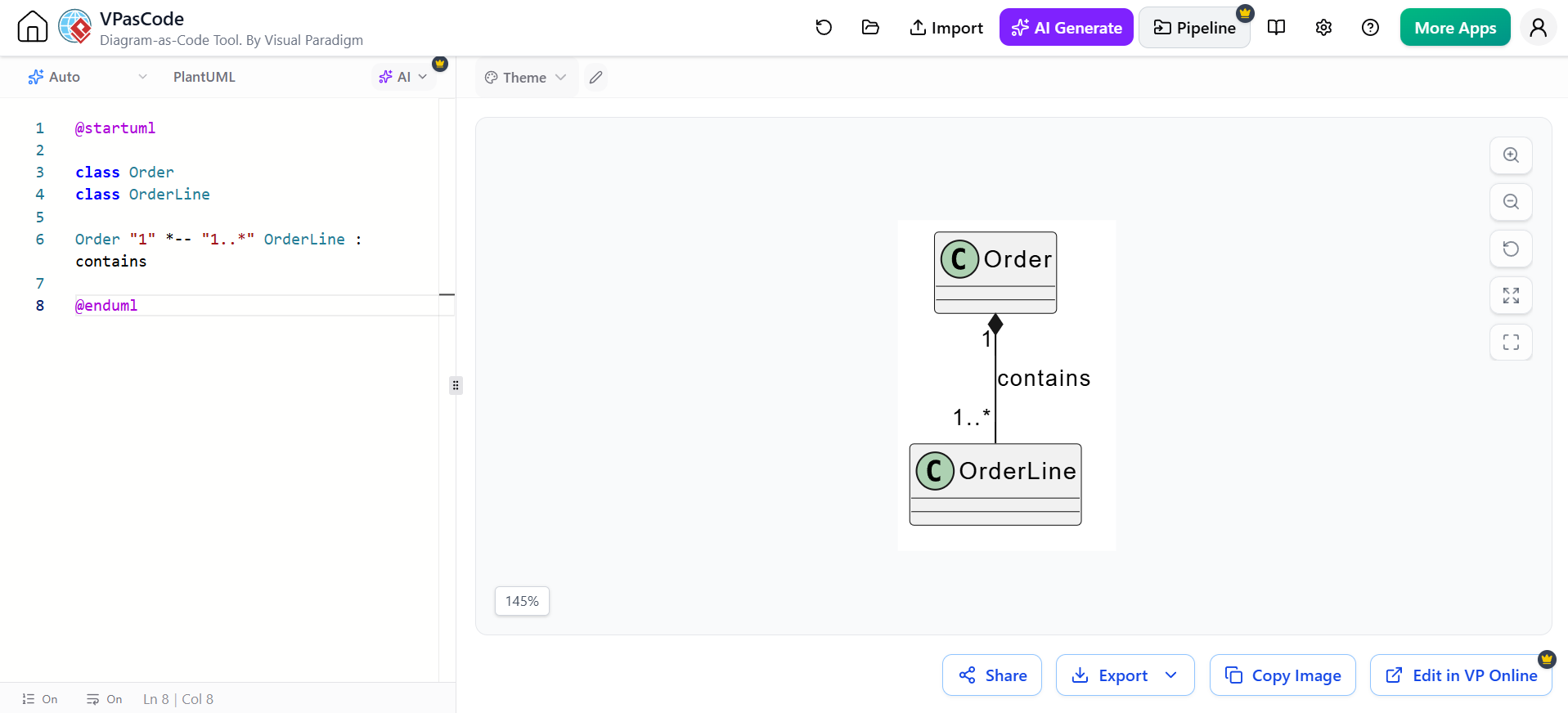
@startuml

class Order
class OrderLine

Order "1" *-- "1..*" OrderLine : contains

@enduml
In this example, an OrderLine belongs to a particular Order. If the order is deleted, its order lines are normally deleted as well.
Another example:
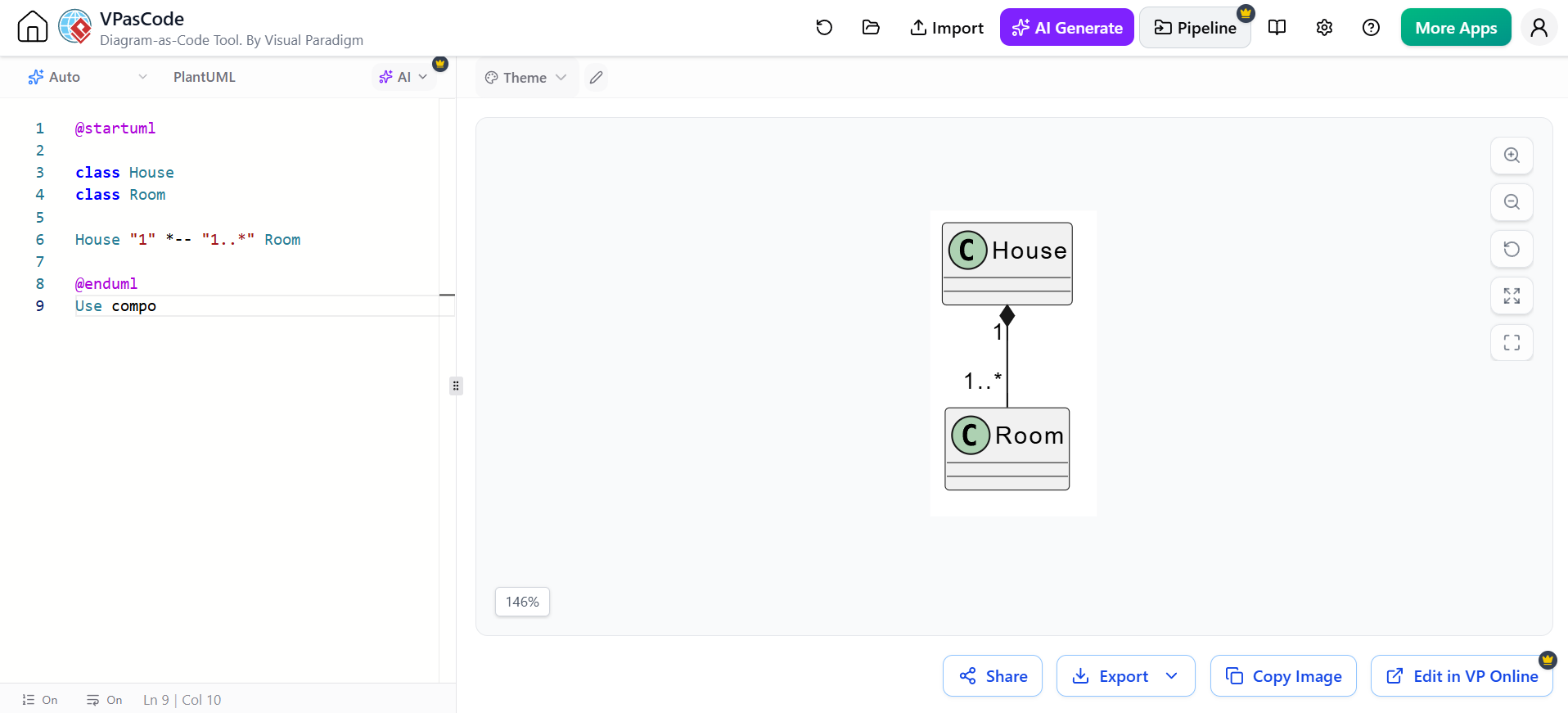
@startuml

class House
class Room

House "1" *-- "1..*" Room

@enduml
Use composition when:
-
The whole controls the lifecycle of the part.
-
The part belongs to one whole at a time.
-
The part has little or no independent meaning outside the whole.
Composition versus aggregation
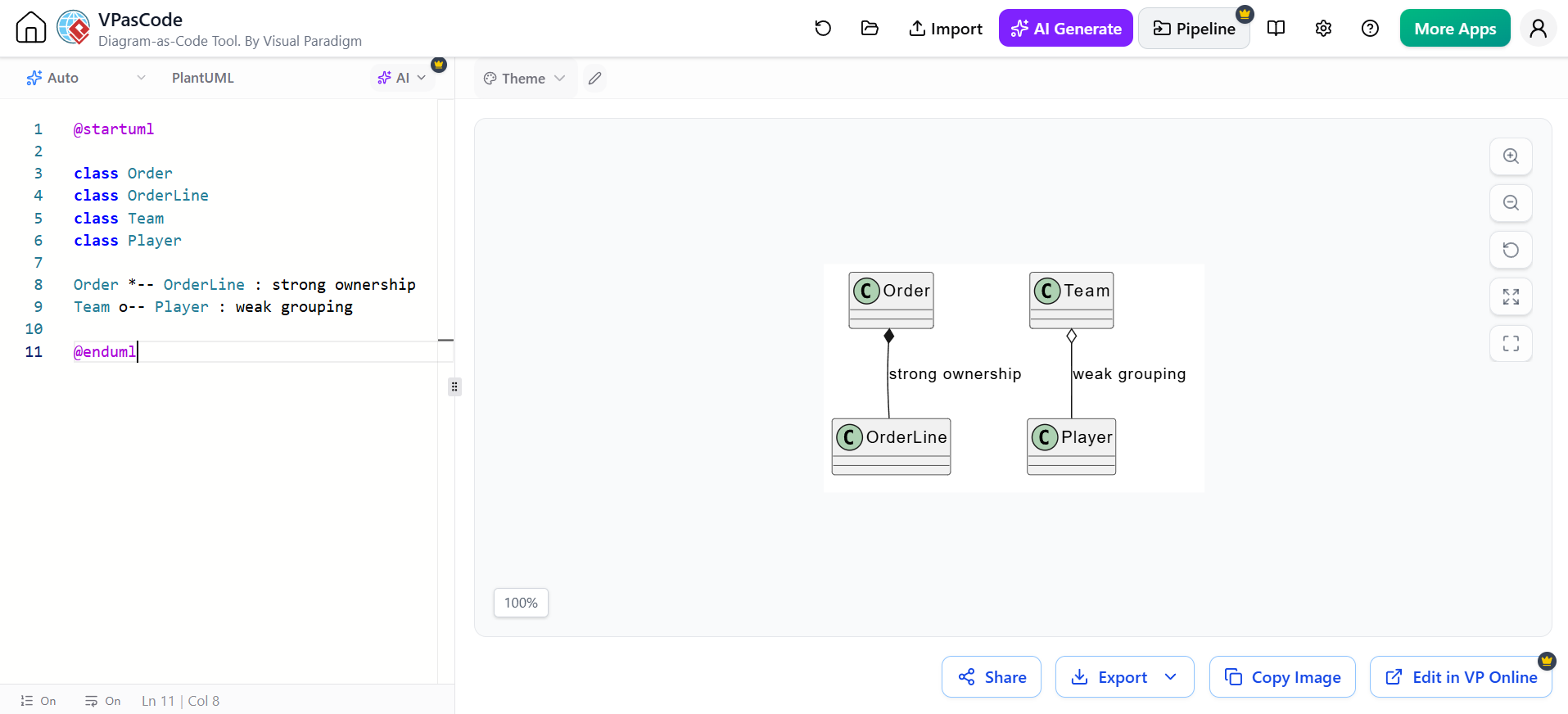
@startuml

class Order
class OrderLine
class Team
class Player

Order *-- OrderLine : strong ownership
Team o-- Player : weak grouping

@enduml
The key distinction is lifecycle ownership:
-
*--means strong composition. -
o--means weaker aggregation. -
--means ordinary association.
6.6 Generalization or Inheritance
Generalization models an “is-a” relationship. It is shown with a solid line and hollow triangle.
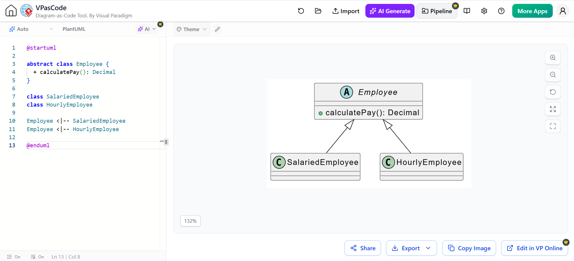
@startuml

abstract class Employee {
  + calculatePay(): Decimal
}

class SalariedEmployee
class HourlyEmployee

Employee <|-- SalariedEmployee
Employee <|-- HourlyEmployee

@enduml
This means:
-
A salaried employee is an employee.
-
An hourly employee is an employee.
Inheritance is appropriate when the subclass genuinely satisfies the behavioral contract of the superclass.
Avoid inheritance merely to reuse a few fields or methods. Composition is often more flexible:
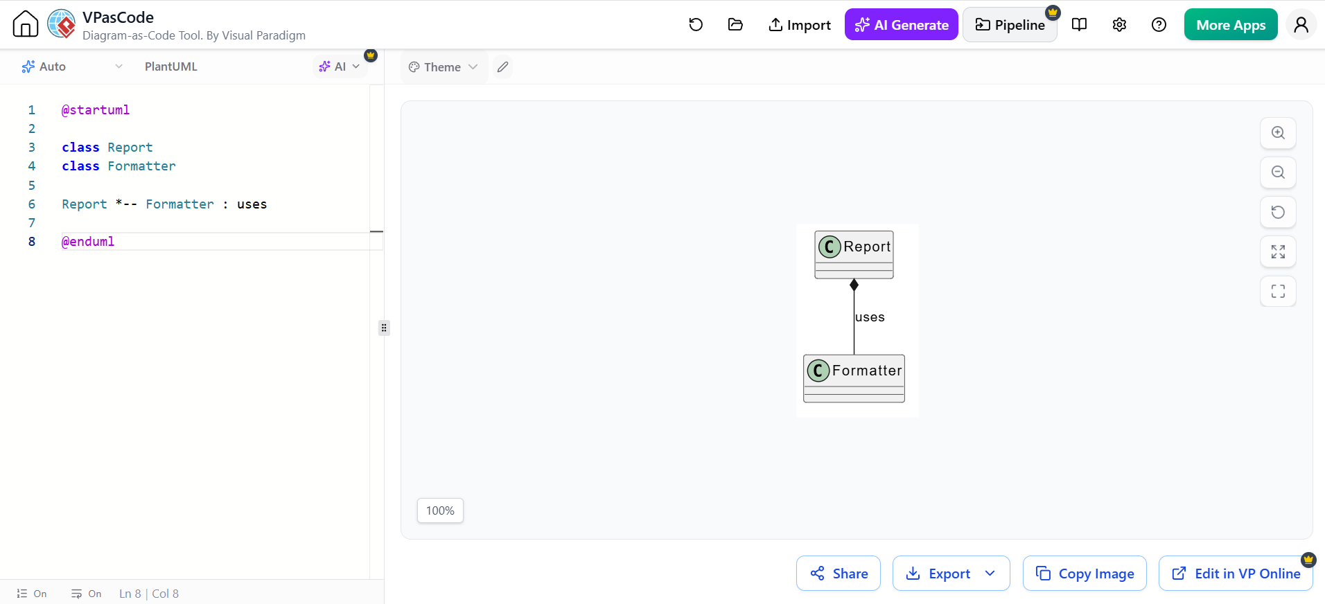
@startuml

class Report
class Formatter

Report *-- Formatter : uses

@enduml
6.7 Realization or Interface Implementation
Realization describes a class implementing an interface. It is shown with a dashed line and hollow triangle.
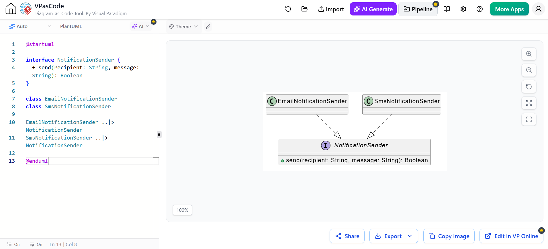
@startuml

interface NotificationSender {
  + send(recipient: String, message: String): Boolean
}

class EmailNotificationSender
class SmsNotificationSender

EmailNotificationSender ..|> NotificationSender
SmsNotificationSender ..|> NotificationSender

@enduml
This design allows the application to depend on the interface rather than on a specific implementation.
6.8 Dependency
A dependency indicates that one class temporarily uses another. It is shown with a dashed arrow.
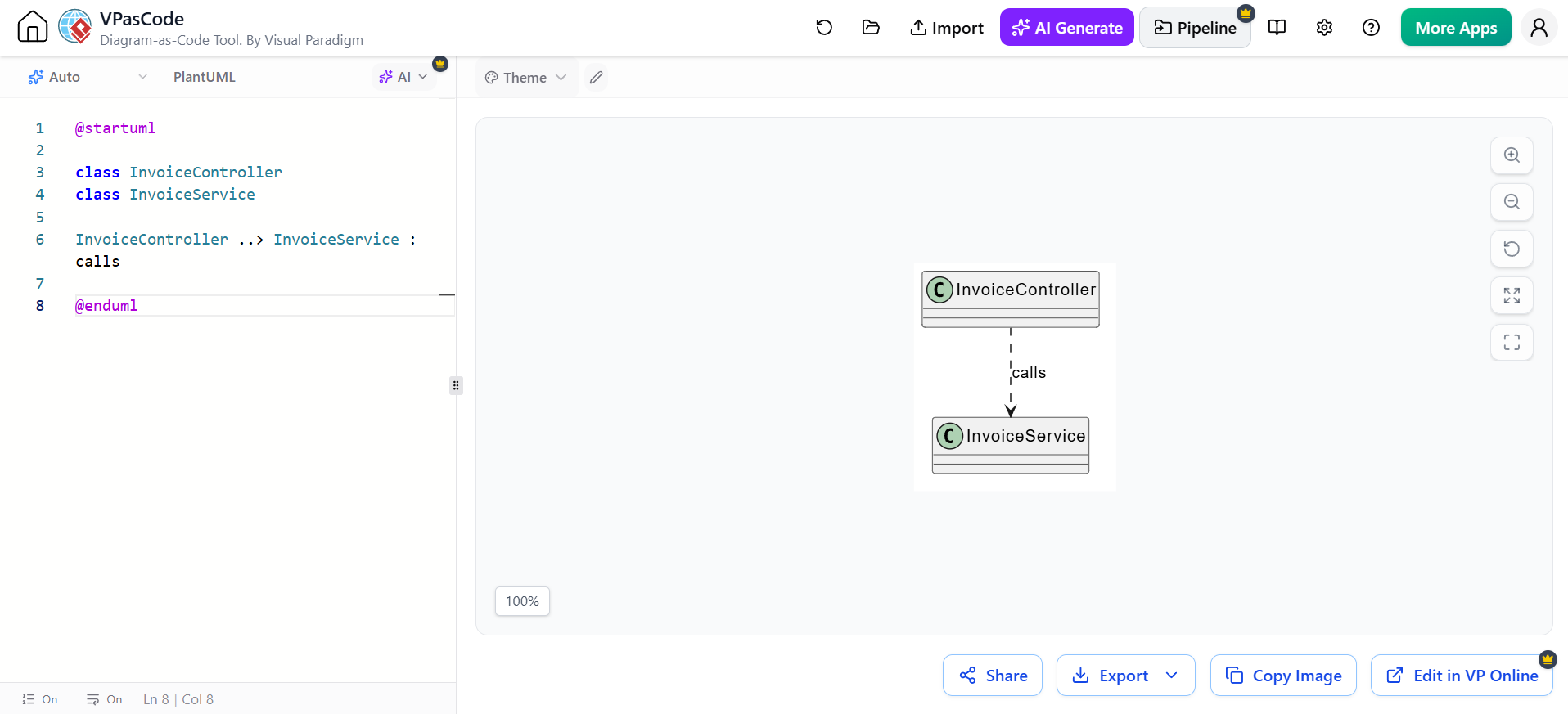
@startuml

class InvoiceController
class InvoiceService

InvoiceController ..> InvoiceService : calls

@enduml
A dependency may occur when a class:
-
Accepts another class as a method parameter
-
Creates a temporary object
-
Calls a static operation
-
Uses another service without storing it as a long-term attribute
Example:
class ReportGenerator {
  + generate(formatter: Formatter): Document
}

ReportGenerator ..> Formatter
A dependency is weaker than an association because the using class may not retain a reference to the used class.
7. Stereotypes
Stereotypes extend UML with additional semantic labels.
They are written between double angle brackets:
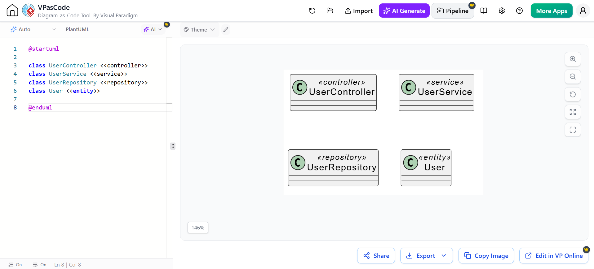
@startuml

class UserController <<controller>>
class UserService <<service>>
class UserRepository <<repository>>
class User <<entity>>

@enduml
Common stereotypes include:
-
<<entity>> -
<<service>> -
<<controller>> -
<<repository>> -
<<interface>> -
<<abstract>> -
<<enumeration>> -
<<DTO>>
Stereotypes are useful when the diagram communicates architecture or design roles, not just domain concepts.
7.1 Enumerations
An enumeration defines a fixed set of values.
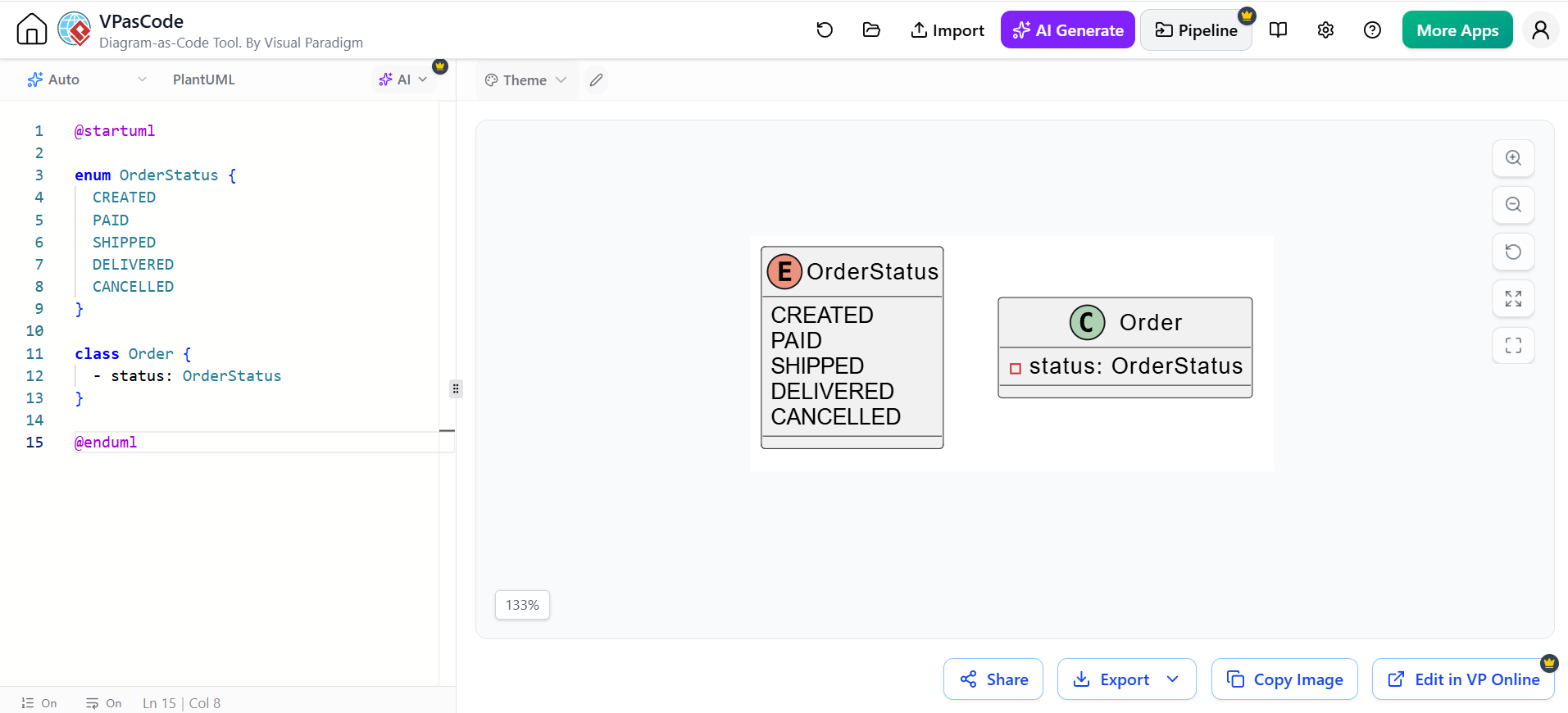
@startuml

enum OrderStatus {
  CREATED
  PAID
  SHIPPED
  DELIVERED
  CANCELLED
}

class Order {
  - status: OrderStatus
}

@enduml
Enumerations are especially useful for:
-
Status values
-
Categories
-
Permission levels
-
Types of payment
-
Workflow states
7.2 Data Transfer Objects
A DTO carries data between application boundaries.
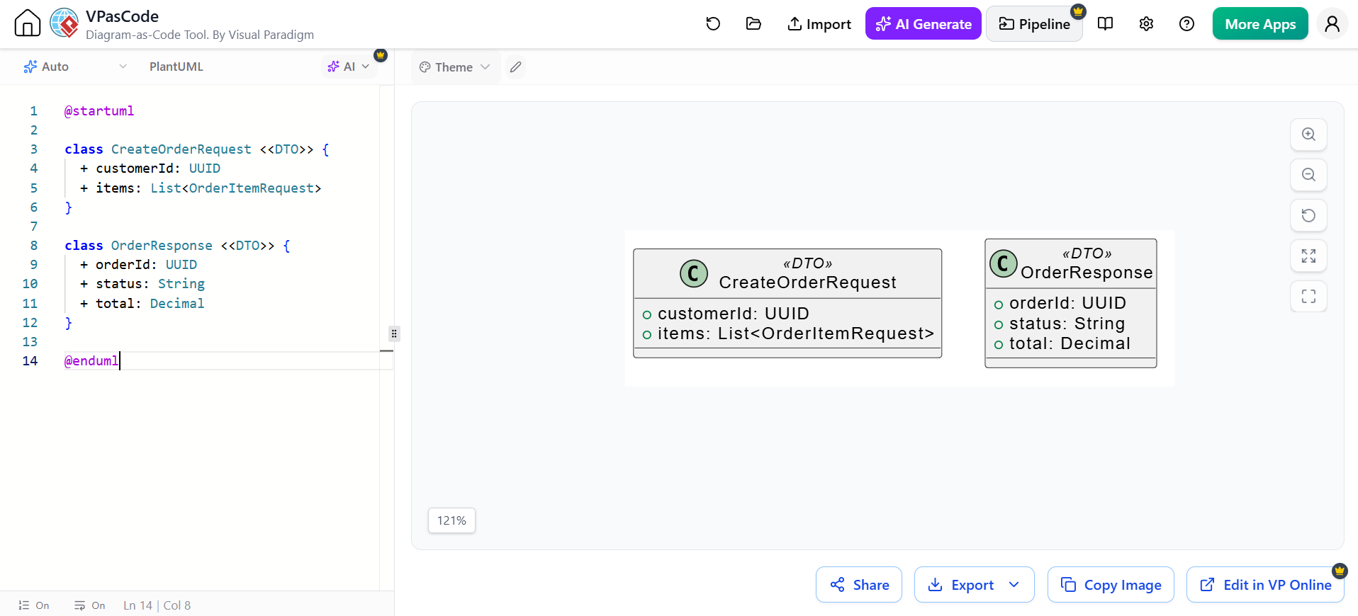
@startuml

class CreateOrderRequest <<DTO>> {
  + customerId: UUID
  + items: List<OrderItemRequest>
}

class OrderResponse <<DTO>> {
  + orderId: UUID
  + status: String
  + total: Decimal
}

@enduml
Distinguish DTOs from domain entities if the architecture uses both.
7.3 Packages
Packages group related classes and reduce visual complexity.
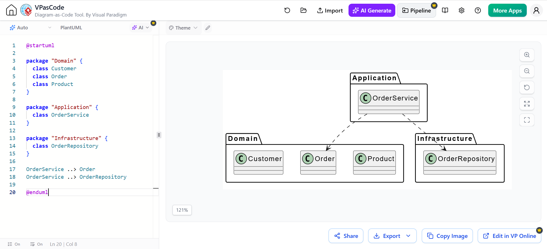
@startuml

package "Domain" {
  class Customer
  class Order
  class Product
}

package "Application" {
  class OrderService
}

package "Infrastructure" {
  class OrderRepository
}

OrderService ..> Order
OrderService ..> OrderRepository

@enduml
Packages can represent:
-
Bounded contexts
-
Application layers
-
Modules
-
Subsystems
-
Namespaces
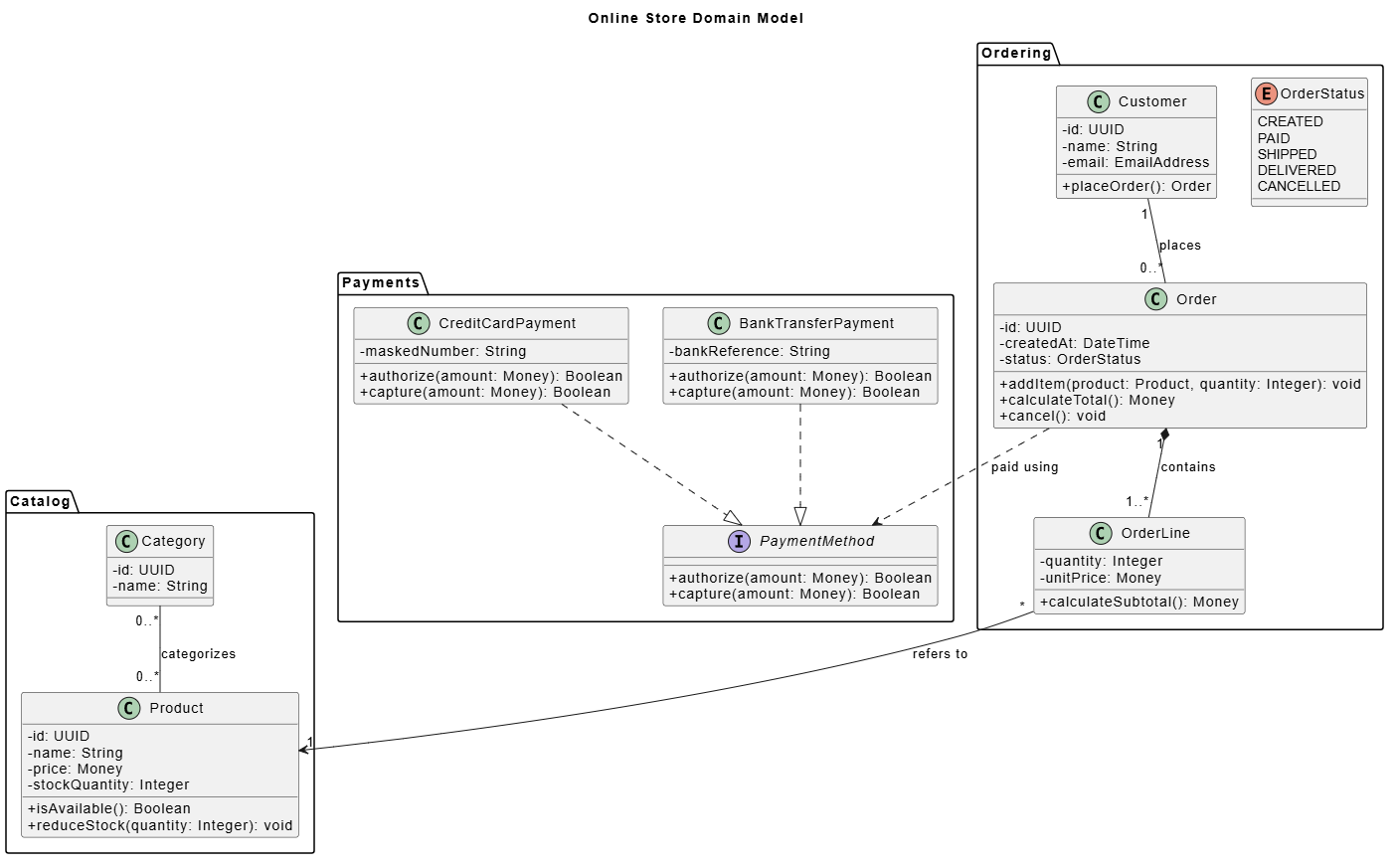
8. A Complete Example: Online Store
The following model combines classes, attributes, operations, inheritance, composition, interfaces, and multiplicities.
@startuml
title Online Store Domain Model

skinparam classAttributeIconSize 0

package "Catalog" {
  class Product {
    - id: UUID
    - name: String
    - price: Money
    - stockQuantity: Integer

    + isAvailable(): Boolean
    + reduceStock(quantity: Integer): void
  }

  class Category {
    - id: UUID
    - name: String
  }

  Category "0..*" -- "0..*" Product : categorizes
}

package "Ordering" {
  class Customer {
    - id: UUID
    - name: String
    - email: EmailAddress

    + placeOrder(): Order
  }

  class Order {
    - id: UUID
    - createdAt: DateTime
    - status: OrderStatus

    + addItem(product: Product, quantity: Integer): void
    + calculateTotal(): Money
    + cancel(): void
  }

  class OrderLine {
    - quantity: Integer
    - unitPrice: Money

    + calculateSubtotal(): Money
  }

  enum OrderStatus {
    CREATED
    PAID
    SHIPPED
    DELIVERED
    CANCELLED
  }

  Customer "1" -- "0..*" Order : places
  Order "1" *-- "1..*" OrderLine : contains
  OrderLine "*" --> "1" Product : refers to
}

package "Payments" {
  interface PaymentMethod {
    + authorize(amount: Money): Boolean
    + capture(amount: Money): Boolean
  }

  class CreditCardPayment {
    - maskedNumber: String

    + authorize(amount: Money): Boolean
    + capture(amount: Money): Boolean
  }

  class BankTransferPayment {
    - bankReference: String

    + authorize(amount: Money): Boolean
    + capture(amount: Money): Boolean
  }

  CreditCardPayment ..|> PaymentMethod
  BankTransferPayment ..|> PaymentMethod
  Order ..> PaymentMethod : paid using
}

@enduml
This diagram expresses several important design decisions:
-
A customer places zero or more orders.
-
An order is composed of one or more order lines.
-
An order line references exactly one product.
-
Products may belong to multiple categories.
-
Payment methods are represented by an interface.
-
Credit card and bank transfer payments implement that interface.
-
An order depends on a payment method without necessarily owning it.
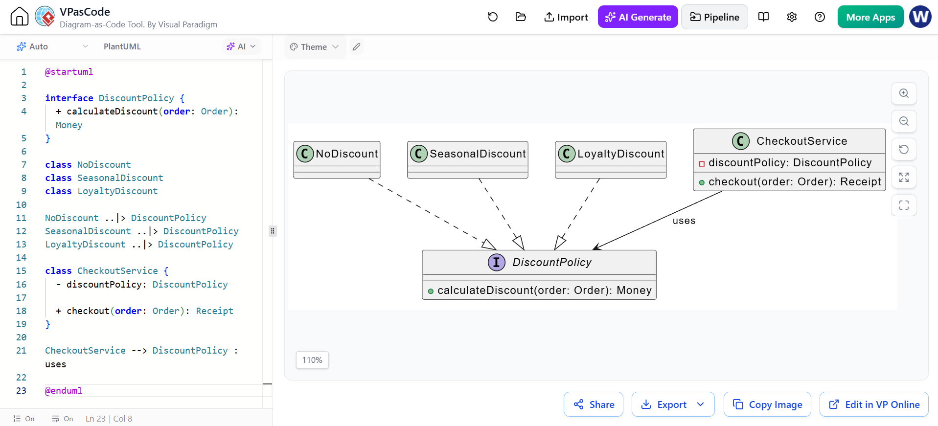
9. Abstract Classes and Polymorphism
Polymorphism allows different classes to be used through a common abstraction.
@startuml

interface DiscountPolicy {
  + calculateDiscount(order: Order): Money
}

class NoDiscount
class SeasonalDiscount
class LoyaltyDiscount

NoDiscount ..|> DiscountPolicy
SeasonalDiscount ..|> DiscountPolicy
LoyaltyDiscount ..|> DiscountPolicy

class CheckoutService {
  - discountPolicy: DiscountPolicy

  + checkout(order: Order): Receipt
}

CheckoutService --> DiscountPolicy : uses

@enduml
The CheckoutService does not need to know whether the policy is seasonal, loyalty-based, or no discount. This reduces coupling and improves extensibility.
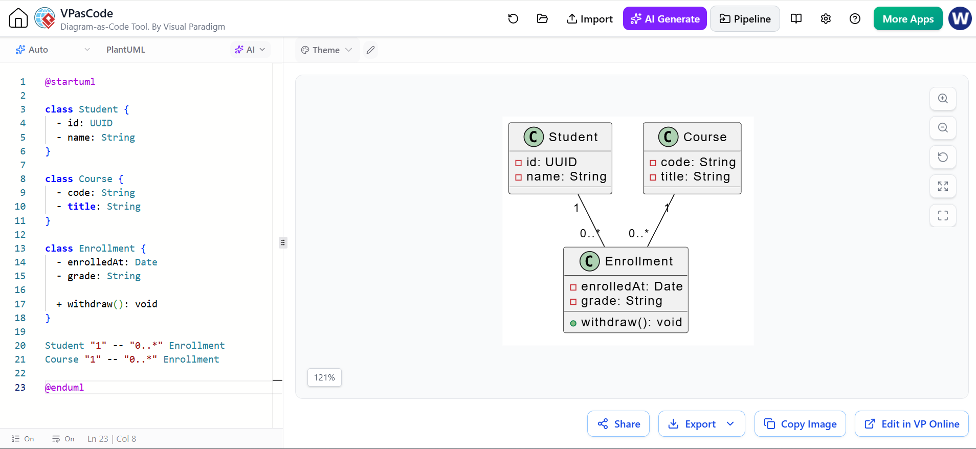
10. Association Classes
Sometimes a relationship has its own data or behavior. In that case, represent it as a separate class.
For example, the relationship between a student and a course may have an enrollment date and grade.
@startuml

class Student {
  - id: UUID
  - name: String
}

class Course {
  - code: String
  - title: String
}

class Enrollment {
  - enrolledAt: Date
  - grade: String

  + withdraw(): void
}

Student "1" -- "0..*" Enrollment
Course "1" -- "0..*" Enrollment

@enduml
Instead of modeling a simple many-to-many relationship:
the Enrollment class makes the relationship explicit and gives it a place for its own attributes.
11. PlantUML Syntax Essentials
A basic PlantUML document has this structure:
@startuml

' Diagram elements go here

@enduml
Comments begin with an apostrophe:
Declaring classes
class Customer
abstract class Account
interface Repository
enum Status
Adding members
class Customer {
  - id: UUID
  + getId(): UUID
}
Relationships
A -- B       ' Association
A --> B      ' Directed association
A o-- B      ' Aggregation
A *-- B      ' Composition
A <|-- B     ' Inheritance
A ..|> B     ' Realization
A ..> B      ' Dependency
A .. B       ' Dashed association
Labels and multiplicities
Customer "1" -- "0..*" Order : places
Order "1" *-- "1..*" OrderLine : contains
Notes
note right of Customer
  A registered buyer
  in the online store.
end note
Or:
note "An order must contain at least one line." as OrderNote
Order .. OrderNote
Direction hints
PlantUML automatically lays out diagrams, but direction hints can improve readability:
Customer -right-> Order
Order -down-> Payment
You can also use:
Example:
@startuml

left to right direction

class Customer
class Order
class Payment

Customer --> Order
Order --> Payment

@enduml
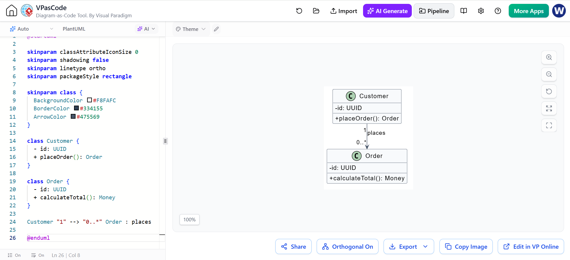
12. Improving PlantUML Readability
For larger diagrams, use styling and layout controls.
@startuml

skinparam classAttributeIconSize 0
skinparam shadowing false
skinparam linetype ortho
skinparam packageStyle rectangle

skinparam class {
  BackgroundColor #F8FAFC
  BorderColor #334155
  ArrowColor #475569
}

class Customer {
  - id: UUID
  + placeOrder(): Order
}

class Order {
  - id: UUID
  + calculateTotal(): Money
}

Customer "1" --> "0..*" Order : places

@enduml
Useful settings include:
-
skinparam classAttributeIconSize 0— simplifies attribute display -
skinparam shadowing false— removes visual shadows -
skinparam linetype ortho— uses more rectangular connectors -
left to right direction— changes the main layout direction -
together { ... }— encourages related elements to stay together
Example:
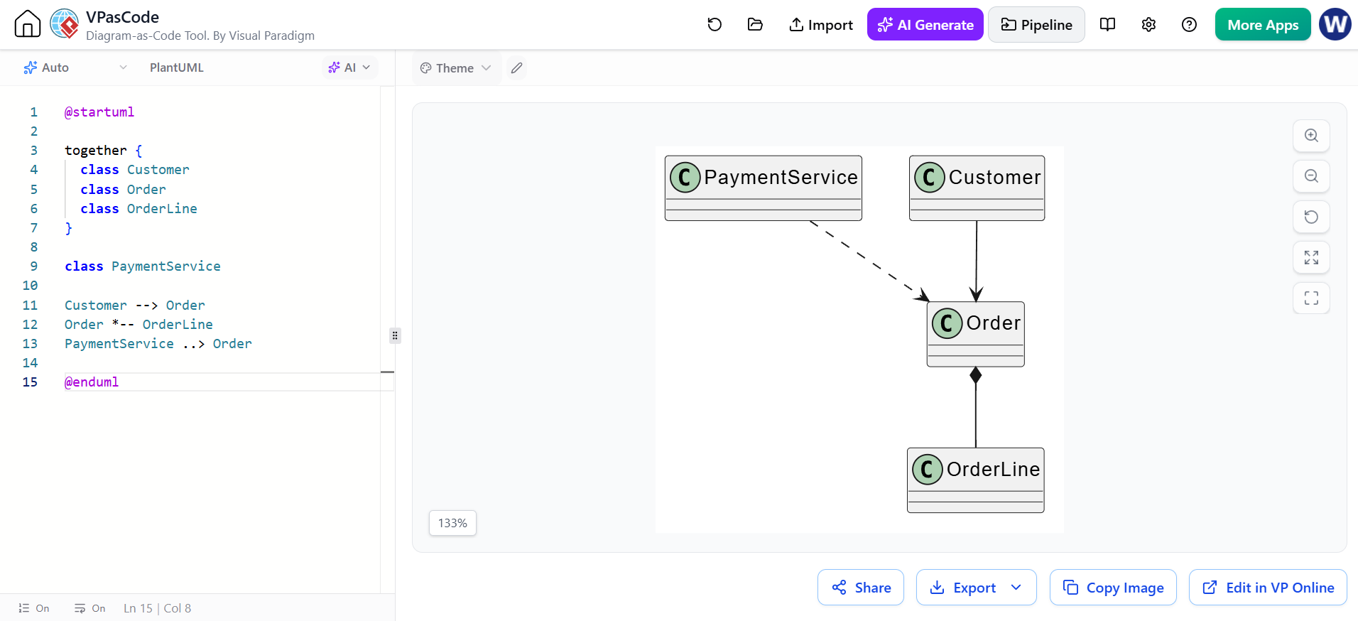
@startuml

together {
  class Customer
  class Order
  class OrderLine
}

class PaymentService

Customer --> Order
Order *-- OrderLine
PaymentService ..> Order

@enduml
13. Modeling Workflow
A practical modeling process is:
Step 1: Define the purpose
Decide what the diagram is meant to communicate.
Possible purposes include:
-
Domain understanding
-
Database-oriented design
-
Application architecture
-
API structure
-
Code review
-
Teaching or documentation
A diagram intended for business stakeholders should contain fewer implementation details than one intended for developers.
Step 2: Identify candidate classes
Extract important nouns from the requirements:
A customer places an order containing products.
An order is paid using a payment method.
Candidate classes:
Customer
Order
Product
PaymentMethod
Do not automatically turn every noun into a class. Validate each candidate by asking:
-
Does it have its own identity?
-
Does it have important data?
-
Does it own meaningful behavior?
-
Does it participate in important relationships?
-
Does it need to be modeled independently?
Step 3: Assign responsibilities
For every class, identify what it knows and what it does.
Order:
- Knows its order lines and status
- Calculates its total
- Can be cancelled

Product:
- Knows its price and stock
- Can determine whether it is available
Step 4: Add attributes
Add only attributes that support the purpose of the diagram.
Step 5: Add operations
Focus on significant domain behavior rather than every technical method.
Step 6: Add relationships
Choose the weakest relationship that accurately communicates the design:
-
Dependency
-
Association
-
Aggregation or composition
-
Inheritance or realization where appropriate
Step 7: Add multiplicities
Multiplicity exposes missing business rules and ambiguous requirements.
For example:
is more informative than:
Step 8: Review responsibilities and coupling
Look for:
-
Classes with too many responsibilities
-
Classes with no meaningful behavior
-
Excessive dependencies
-
Incorrect ownership
-
Inheritance used only for code reuse
-
Missing classes for important relationships
14. Using Visual Paradigm UML
Visual Paradigm supports visual UML modeling, class diagrams, code engineering, documentation, collaboration, and other modeling workflows. Its current platform also includes AI-enabled diagram generation and guided class-diagram workflows.
A typical Visual Paradigm workflow is:
-
Create or open a project.
-
Create a UML class diagram.
-
Add classes from the diagram palette.
-
Add attributes and operations.
-
Connect classes with relationships.
-
Set multiplicities and role names.
-
Organize classes into packages.
-
Apply layout and formatting.
-
Add notes or constraints.
-
Review the model and export documentation or diagrams.
Creating a class diagram
In Visual Paradigm:
-
Start a new project or open an existing project.
-
Create a UML class diagram.
-
Drag a class element onto the diagram.
-
Enter the class name.
-
Add attributes and operations through the class specification or inline editing.
-
Select the appropriate relationship tool from the palette.
The exact menu names can vary between Visual Paradigm Desktop and Visual Paradigm Online, so use the workflow appropriate to your edition.
Recommended Visual Paradigm practices
Use packages: Group related classes by domain or architectural layer.
Domain
  Customer
  Order
  Product

Application
  OrderService
  PaymentService

Infrastructure
  OrderRepository
Use model elements consistently: Avoid representing the same concept as both a class and a database table unless the diagram explicitly covers both perspectives.
Use relationship properties: Configure:
-
Multiplicity
-
Role names
-
Navigability
-
Relationship labels
-
Aggregation or composition kind
Use auto-layout as a starting point: Automatic layout can improve readability, but manually adjust important diagrams afterward.
Add documentation: Notes and descriptions are valuable when a relationship or constraint is not obvious from the notation.
Use traceability when needed: In larger projects, connect classes to requirements, use cases, sequence diagrams, or code artifacts. Visual Paradigm describes traceability and code engineering as part of its professional modeling workflow.
15. AI-Assisted UML Modeling
AI can speed up the first draft of a class diagram by converting natural-language requirements into candidate classes, attributes, operations, and relationships.
Visual Paradigm’s AI-assisted class diagram workflow is described as a guided process that can help define scope, identify classes, add attributes and operations, establish relationships, generate notes, render the diagram, and produce an analysis report. It can also expose or export PlantUML-based diagram content.
A suitable prompt might be:
Create a UML class diagram for an online library system.

The system allows members to search for books, borrow available copies,
return borrowed copies, and pay overdue fines.

Include:
- Member, Book, BookCopy, Loan, and Fine classes
- Important attributes and operations
- Multiplicities
- Composition where lifecycle ownership is appropriate
- An abstract NotificationService with email and SMS implementations
- Clear relationship labels
The AI-generated result should be treated as a draft, not as an authoritative design.
AI review checklist
After generation, inspect the diagram for:
-
Duplicate classes
-
Missing classes
-
Incorrect multiplicities
-
Wrong composition relationships
-
Excessive inheritance
-
Anemic classes with only data
-
Operations assigned to the wrong class
-
Technical classes mixed with domain classes
-
Unclear naming
-
Relationships inferred from assumptions rather than requirements
AI can suggest that Order composes Customer, for example, even though a customer normally exists independently of an order. Always verify lifecycle semantics.
Prompting for better results
Include:
-
System scope
-
Primary actors
-
Important business rules
-
Expected classes
-
Explicit exclusions
-
Required relationship types
-
Desired level of detail
-
Target audience
Example:
Model only the domain layer. Do not include controllers, database tables,
repositories, frameworks, or UI classes. Show entities, value objects,
domain services, business operations, and multiplicities.
For architecture:
Create a UML class diagram for a layered e-commerce application.
Separate Domain, Application, and Infrastructure packages.
Show dependencies from Application to Domain and interfaces for
Infrastructure implementations. Avoid showing every getter and setter.
16. AI-Generated PlantUML Review Example
Suppose an AI proposes:
@startuml

class Customer
class Order
class Payment

Customer *-- Order
Order *-- Payment

@enduml
This may be incorrect.
Questions to ask:
-
Does an order own the customer’s lifecycle?
-
Can the same customer have multiple orders?
-
Is payment part of the order lifecycle?
-
Can a payment be refunded or audited independently?
-
Is payment a transaction, a value object, or an external service?
A more realistic model might be:
@startuml

class Customer {
  - id: UUID
}

class Order {
  - id: UUID
  - status: OrderStatus
}

class Payment {
  - id: UUID
  - amount: Money
  - status: PaymentStatus
}

Customer "1" -- "0..*" Order : places
Order "1" -- "0..*" Payment : has transactions

@enduml
The difference is important:
-
A customer exists independently of an order.
-
An order may have multiple payment transactions.
-
A payment may need its own identity and lifecycle.
-
Ordinary association communicates the model more accurately than composition.
17. Common Modeling Mistakes
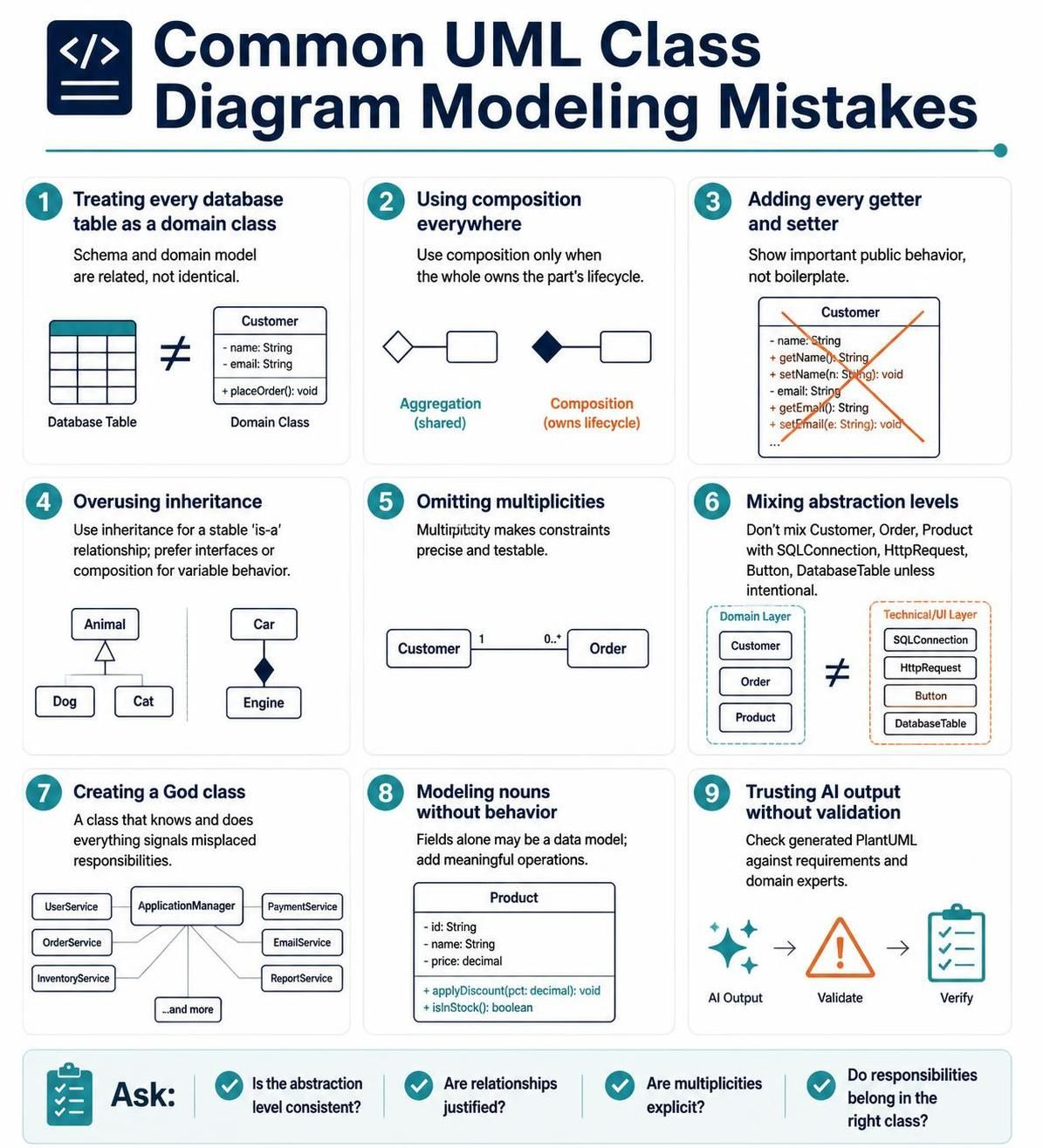
Mistake 1: Treating every database table as a domain class
A database schema and a domain model are related but not identical. A join table may be better modeled as an association class, and several database tables may represent one domain concept.
Mistake 2: Using composition everywhere
Composition is not simply a stronger-looking association. Use it only when the whole owns the part’s lifecycle.
Mistake 3: Adding every getter and setter
Large diagrams become unreadable when they contain boilerplate operations. Show important public behavior instead.
Mistake 4: Overusing inheritance
Inheritance should express a stable “is-a” relationship. Use interfaces or composition when behavior is variable or interchangeable.
Mistake 5: Omitting multiplicities
An unlabeled relationship hides important constraints. Multiplicity makes the model testable and precise.
Mistake 6: Mixing abstraction levels
Avoid combining:
Customer
Order
Product
with:
SQLConnection
HttpRequest
Button
DatabaseTable
unless the diagram intentionally explains a specific implementation architecture.
Mistake 7: Creating a “God class”
A class such as ApplicationManager or SystemController that knows and does everything usually indicates misplaced responsibilities.
Mistake 8: Modeling nouns without behavior
A domain model containing only classes and fields may be a data model rather than a useful object-oriented design. Add meaningful operations where behavior belongs.
Mistake 9: Trusting AI output without validation
AI can produce syntactically valid PlantUML that represents incorrect business rules. Validate the design against requirements and domain experts.
18. Quality Checklist
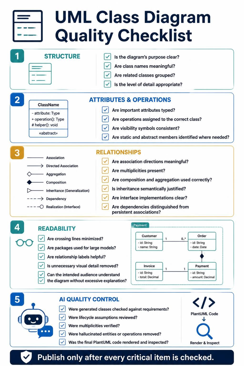
Before publishing a class diagram, verify:
Structure
-
Is the diagram’s purpose clear?
-
Are class names meaningful?
-
Are related classes grouped?
-
Is the level of detail appropriate?
Attributes and operations
-
Are important attributes typed?
-
Are operations assigned to the correct class?
-
Are visibility symbols used consistently?
-
Are static and abstract members identified where needed?
Relationships
-
Are association directions meaningful?
-
Are multiplicities present?
-
Are composition and aggregation used correctly?
-
Is inheritance semantically justified?
-
Are interface implementations clear?
-
Are dependencies distinguished from persistent associations?
Readability
-
Are crossing lines minimized?
-
Are packages used for large models?
-
Are relationship labels helpful?
-
Is there unnecessary visual detail?
-
Can the intended audience understand the diagram without excessive explanation?
AI quality control
-
Were generated classes checked against the requirements?
-
Were lifecycle assumptions reviewed?
-
Were multiplicities verified?
-
Were hallucinated entities or operations removed?
-
Was the final PlantUML code rendered and inspected?
19. Compact Reference Example
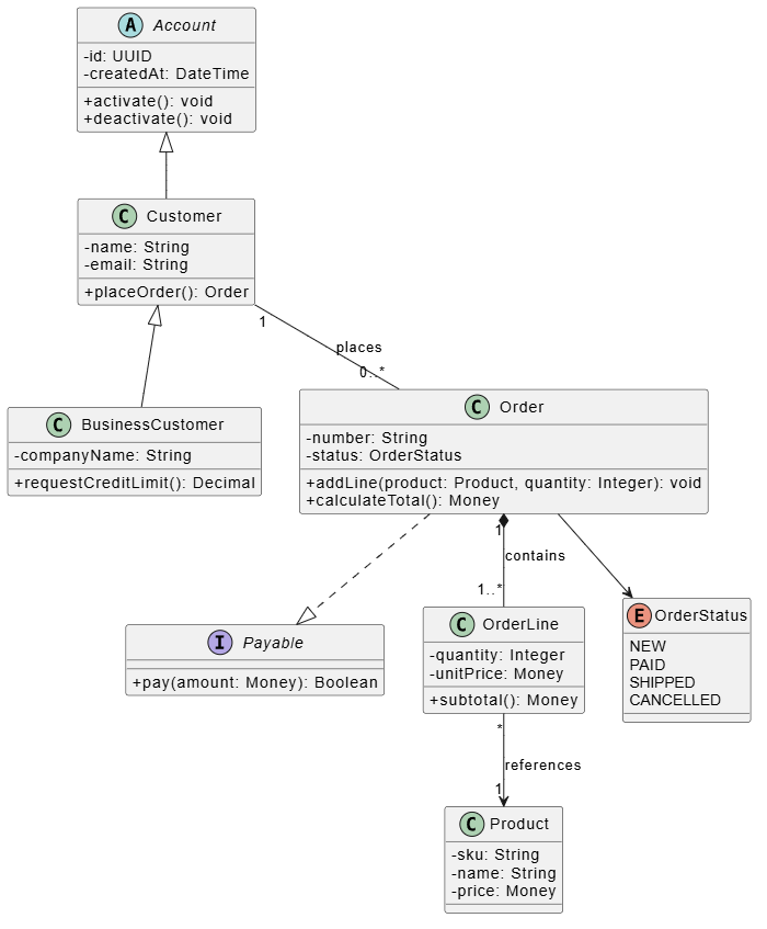
@startuml

skinparam classAttributeIconSize 0

abstract class Account {
  - id: UUID
  - createdAt: DateTime

  + activate(): void
  + deactivate(): void
}

class Customer {
  - name: String
  - email: String

  + placeOrder(): Order
}

class BusinessCustomer {
  - companyName: String

  + requestCreditLimit(): Decimal
}

interface Payable {
  + pay(amount: Money): Boolean
}

class Order {
  - number: String
  - status: OrderStatus

  + addLine(product: Product, quantity: Integer): void
  + calculateTotal(): Money
}

class OrderLine {
  - quantity: Integer
  - unitPrice: Money

  + subtotal(): Money
}

class Product {
  - sku: String
  - name: String
  - price: Money
}

enum OrderStatus {
  NEW
  PAID
  SHIPPED
  CANCELLED
}

Account <|-- Customer
Customer <|-- BusinessCustomer
Customer "1" -- "0..*" Order : places
Order "1" *-- "1..*" OrderLine : contains
OrderLine "*" --> "1" Product : references
Order ..|> Payable
Order --> OrderStatus

@enduml
This compact example demonstrates:
-
Abstract classes
-
Inheritance
-
Interfaces
-
Attributes
-
Operations
-
Composition
-
Associations
-
Dependencies
-
Multiplicity
-
Enumerations
-
Relationship labels
The most effective workflow is to use AI or Visual Paradigm to accelerate the initial model, then refine the result manually using UML semantics, domain rules, and PlantUML code review.
References
- UML in the Age of AI: How Visual Paradigm’s Ecosystem Is Reviving Visual Modeling (2025): Comprehensive guide on how AI transforms UML for agile and enterprise development, including statistics on UML usage and practical AI modeling examples.
- AI UML Tools: Automate UML Design with Intelligence: Practical walkthrough of AI-driven UML generation, covering text-to-diagram workflows, auto-layout optimization, and real project case studies.
- Top Myths About AI UML Generators Debunked for Beginners: Addresses common misconceptions about AI UML tools, including quality concerns, learning value, and suitability for complex enterprise diagrams.
- From Text to Architecture: Accelerating UML Modeling with Generative AI: Explores Visual Paradigm’s core AI capabilities, including prompt-to-diagram generation, conversational chatbot refinement, and AI use case modeling.
- AI Class Diagram Generation: Modeling Entities with UML 2.5 Compliance: Detailed technical guide on generating standards-compliant class diagrams from natural language, including relationship notation and iterative refinement commands.
- Foundations of Modeling & UML: Educational resource covering UML basics, the 14 diagram types, and core concepts like structural vs. behavioral models—useful for understanding fundamentals before adopting AI features.
- A Case Study on Accelerating UML Class Diagram Development with Visual Paradigm’s AI Ecosystem: Real-world fintech case study showing how a team used AI chatbots and VP Desktop to model complex payment systems in days instead of weeks.
- Enhanced AI Composite Structure Diagram Generation in Visual Paradigm AI Chatbot: Release announcement detailing improvements to AI composite structure diagram generation, including stability and detail enhancements.

![How to Model Constraints in UML? [With Examples]](https://www.archimetric.com/wp-content/uploads/2026/04/uml-constraint-example.png "How to Model Constraints in UML? [With Examples]")

 English
 Arabic
 Chinese (Simplified)
 Dutch
Dutch French
 German
 Italian
 Japanese
 Korean
 Portuguese
 Russian
 Spanish