


The user wants me to create a beginner’s guide based on the UML Use Case Diagram Notation Reference image. Let me analyze the image content and create a comprehensive, well-structured guide for beginners.
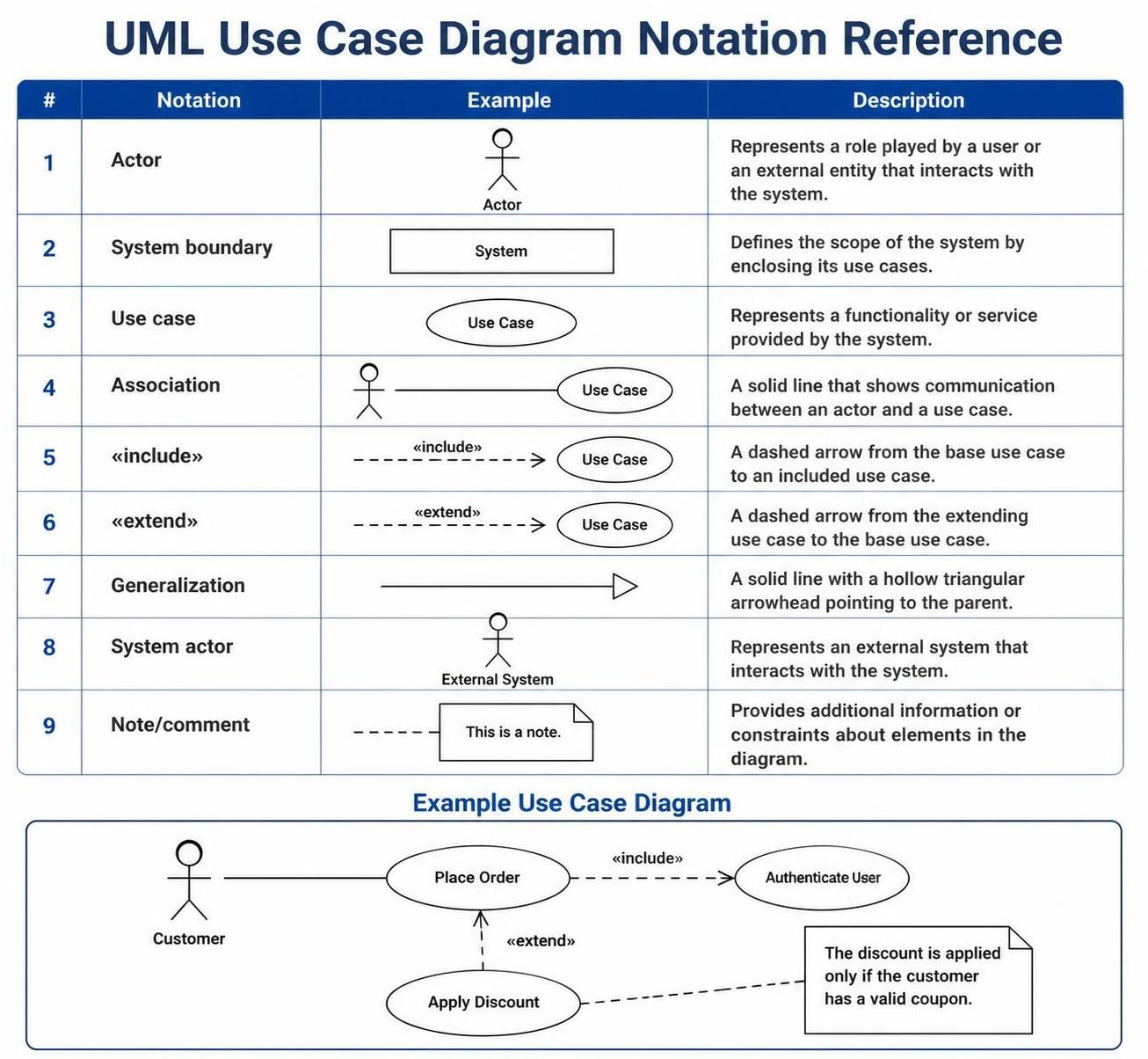
From the use case notation quick reference, we can see:
-
Actor – stick figure representing a user or external entity
-
System boundary – rectangle defining system scope
-
Use case – oval representing functionality/service
-
Association – solid line showing communication between actor and use case
-
«include» – dashed arrow from base use case to included use case
-
«extend» – dashed arrow from extending use case to base use case
-
Generalization – solid line with hollow triangular arrowhead pointing to parent
-
System actor – represents an external system that interacts with the system
-
Note/comment – provides additional information or constraints
The example diagram shows a Customer placing an order, which includes authentication and optionally applies a discount when a valid coupon exists. Now I’ll structure this into a clear, accessible guide that walks beginners through each concept systematically.
📘 Beginner’s Guide to UML Use Case Diagrams
Based on the reference image provided, here is a comprehensive guide to understanding and creating UML Use Case Diagrams — one of the most fundamental tools in software design and requirements gathering.
🔍 What Is a Use Case Diagram?
A Use Case Diagram is a type of UML (Unified Modeling Language) diagram that visually represents how users (called actors) interact with a system to achieve specific goals. It captures the functional requirements of a system from the user’s perspective [[3]].
Think of it as a “big picture” map of what your system does and who uses it — without getting into technical implementation details.
The 9 Key Notations Explained
1. 👤 Actor
-
Symbol: Stick figure
-
Meaning: Represents a role played by a person, organization, or external entity that interacts with the system.
-
Example:
Customer,Admin,Payment Gateway -
💡 An actor is NOT a specific person — it’s a role. Multiple people can play the same actor role.
2. System Boundary
-
Symbol: Rectangle enclosing use cases
-
Meaning: Defines the scope of the system — everything inside the box is part of the system; everything outside is external.
-
This helps clarify what your system is responsible for vs. what it isn’t.
3. ⭕ Use Case
-
Symbol: Oval/Ellipse with a name inside
-
Meaning: Represents a specific functionality or service the system provides.
-
Example:
Place Order,Authenticate User,Apply Discount -
💡 Each use case should describe ONE clear goal from the actor’s perspective.
4. Association
-
Symbol: Solid line connecting an Actor to a Use Case
-
Meaning: Shows that an actor communicates with or participates in a use case.
-
💡 No arrowhead needed — the relationship is bidirectional.
5. 🔗 «include» Relationship
-
Symbol: Dashed arrow labeled
«include»pointing from base → included use case -
Meaning: The base use case always incorporates the behavior of the included use case. It is mandatory.
-
Example:
Place Order→«include»→Authenticate User -
💡 Think: “You CANNOT place an order WITHOUT authenticating first.” [[10]]
6. 🔀 «extend» Relationship
-
Symbol: Dashed arrow labeled
«extend»pointing from extending → base use case -
Meaning: The extending use case adds optional or conditional behavior to the base use case.
-
Example:
Apply Discount→«extend»→Place Order -
💡 Think: “Discount is applied ONLY IF the customer has a valid coupon.” [[14]]
⚠️ Include vs. Extend — Quick Comparison
| Feature | «include» | «extend» |
|---|---|---|
| Behavior | Mandatory | Optional / Conditional |
| Arrow Direction | Base → Included | Extending → Base |
| Base UC Complete? | No (needs included) | Yes (stands alone) |
| Example | Login before ordering | Apply discount if coupon exists |
[[15]]
7. 🔺 Generalization
-
Symbol: Solid line with a hollow triangular arrowhead pointing to the parent
-
Meaning: Shows an “is-a” inheritance relationship between actors or use cases.
-
Example:
Registered Customergeneralizes toCustomer -
💡 The child inherits all behaviors of the parent and may add its own.
8. 🖥️ System Actor (External System)
-
Symbol: Stick figure labeled as an external system
-
Meaning: Represents a non-human external system that interacts with your system.
-
Example:
Payment Gateway,Email Service,Inventory API -
Not all actors are humans! External software systems are actors too.
9. 📝 Note / Comment
-
Symbol: Rectangle with a folded corner, connected by a dashed line
-
Meaning: Provides additional context, constraints, or explanations about any element in the diagram.
-
Example: “The discount is applied only if the customer has a valid coupon.”
-
💡 Use notes to clarify conditions that aren’t obvious from the diagram alone.
Putting It All Together: Example Walkthrough
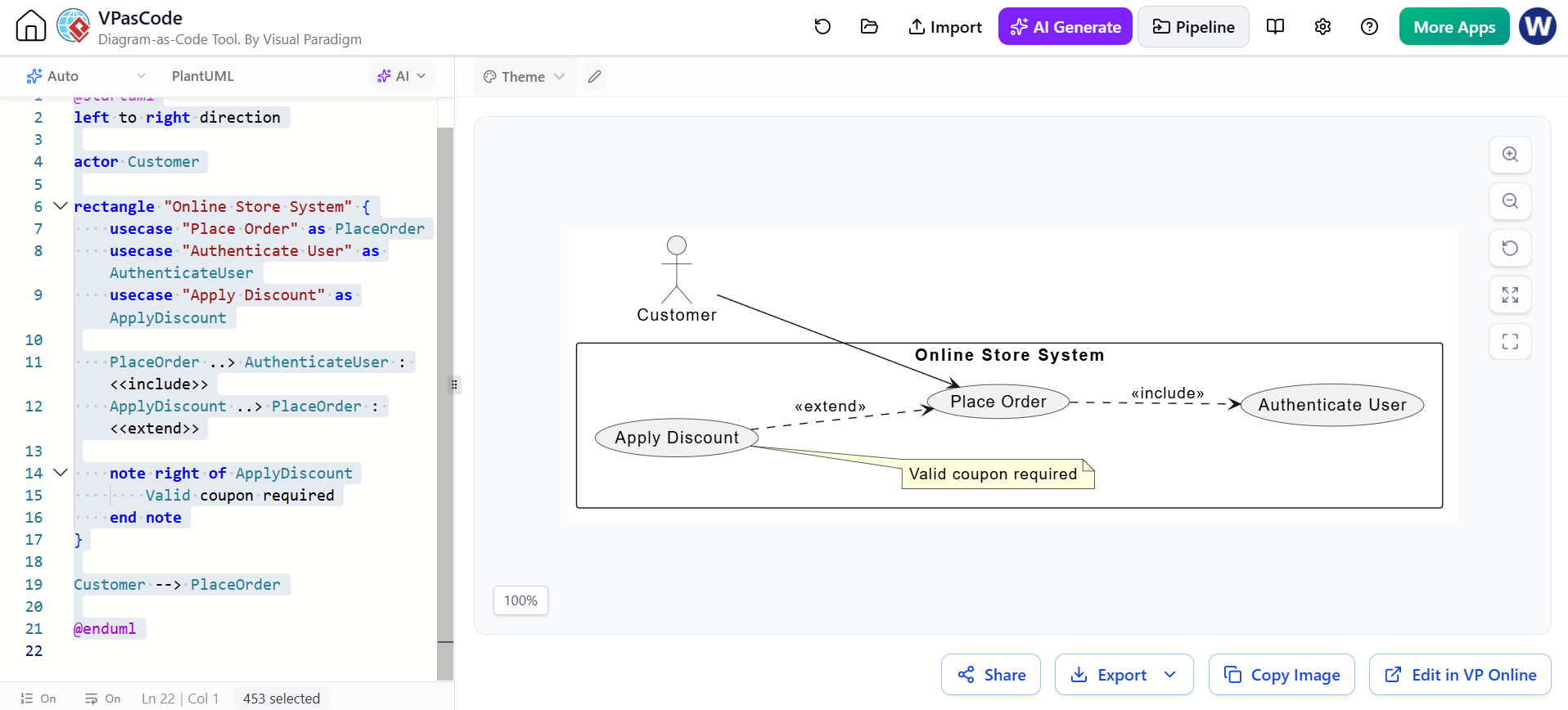
Looking at the Example Use Case Diagram at the bottom of the image:
@startuml
left to right direction

actor Customer

rectangle "Online Store System" {
    usecase "Place Order" as PlaceOrder
    usecase "Authenticate User" as AuthenticateUser
    usecase "Apply Discount" as ApplyDiscount

    PlaceOrder ..> AuthenticateUser : <<include>>
    ApplyDiscount ..> PlaceOrder : <<extend>>

    note right of ApplyDiscount
        Valid coupon required
    end note
}

Customer --> PlaceOrder

@endumlStory: A Customer wants to Place an Order. To do so, they must be authenticated («include»). Optionally, if they have a valid coupon, a discount can be applied («extend»).
✅ Best Practices for Beginners
-
Start simple — Identify actors and their main goals first
-
Name use cases as verb phrases — e.g., “Place Order” not “Order Placement”
-
One goal per use case — Avoid combining multiple functionalities
-
Use «include» for shared mandatory steps — Avoid duplicating common logic
-
Use «extend» sparingly — Only for truly optional/conditional behavior
-
Draw the system boundary — Clearly define what’s in scope
-
Add notes for clarity — Don’t assume everyone understands the context
-
Review with stakeholders — Use case diagrams are communication tools, not just documentation
🛠️ When to Use Use Case Diagrams
-
✅ Gathering functional requirements early in a project
-
✅ Communicating system behavior to non-technical stakeholders
-
✅ Identifying gaps or overlaps in system functionality
-
✅ Planning test scenarios based on user interactions
-
✅ Documenting as-is or to-be system behavior
📌 Summary Cheat Sheet
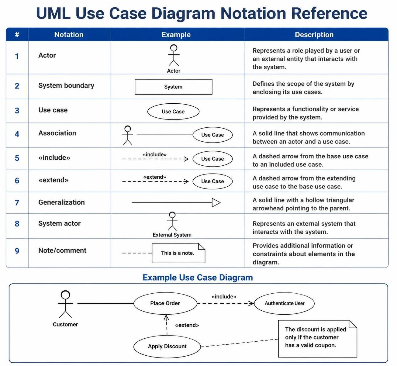
💬 Remember: A Use Case Diagram is a communication tool. Its purpose is to make complex system behavior understandable at a glance. Keep it clean, focused, and always tied back to real user goals!
![How to Model Constraints in UML? [With Examples]](https://www.archimetric.com/wp-content/uploads/2026/04/uml-constraint-example.png "How to Model Constraints in UML? [With Examples]")


 English
 Arabic
 Chinese (Simplified)
 Dutch
Dutch French
 German
 Italian
 Japanese
 Korean
 Portuguese
 Russian
 Spanish