


ArchiMate is an enterprise architecture modeling language for describing business, application, technology, strategy, motivation, physical, and implementation aspects of an organization. It provides a common vocabulary for connecting organizational goals to capabilities, processes, applications, technology, and change initiatives.
ArchiMate-PlantUML combines that language with PlantUML’s text-based diagramming syntax. The result is a practical “diagram as code” workflow: models can be edited in a text editor, reviewed through Git, generated consistently, and refined with an AI chatbot. The official ArchiMate-PlantUML library provides macros for ArchiMate elements, relationships, groups, nesting, themes, and layout helpers.
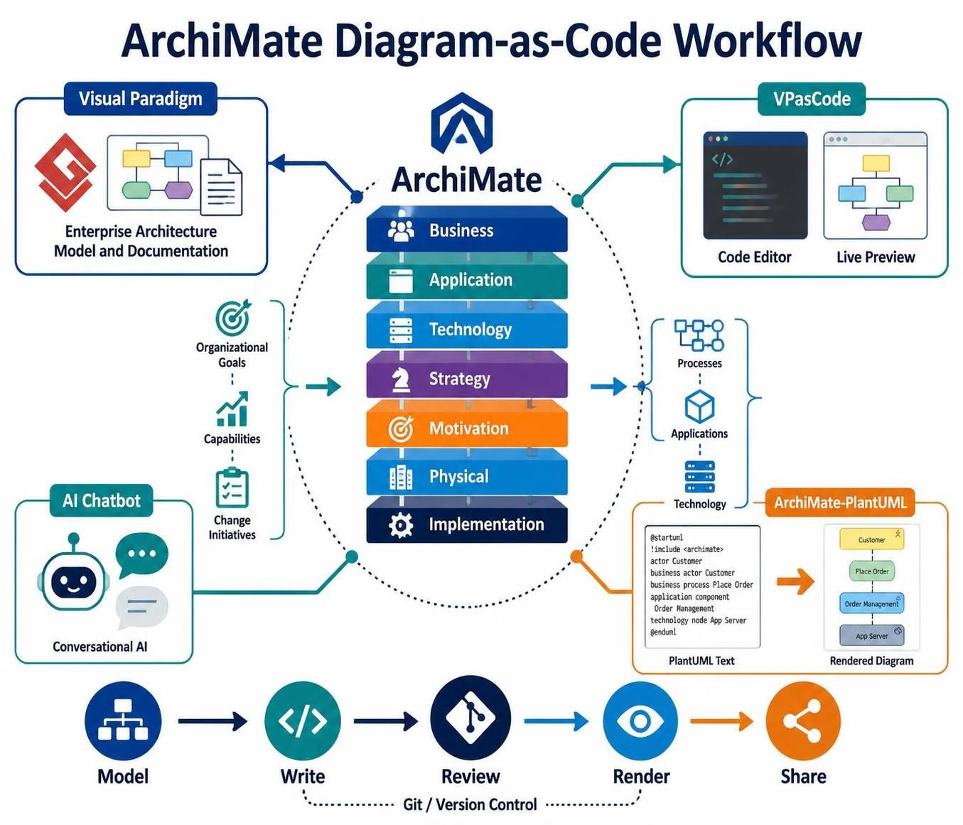
This guide uses:
-
Visual Paradigm for formal modeling, documentation, viewpoints, and stakeholder-oriented diagrams
-
VPasCode for fast PlantUML authoring and live preview
-
An AI chatbot for drafting, explaining, reviewing, and refactoring model code
-
ArchiMate-PlantUML for rendering ArchiMate diagrams from text
1. What ArchiMate is used for
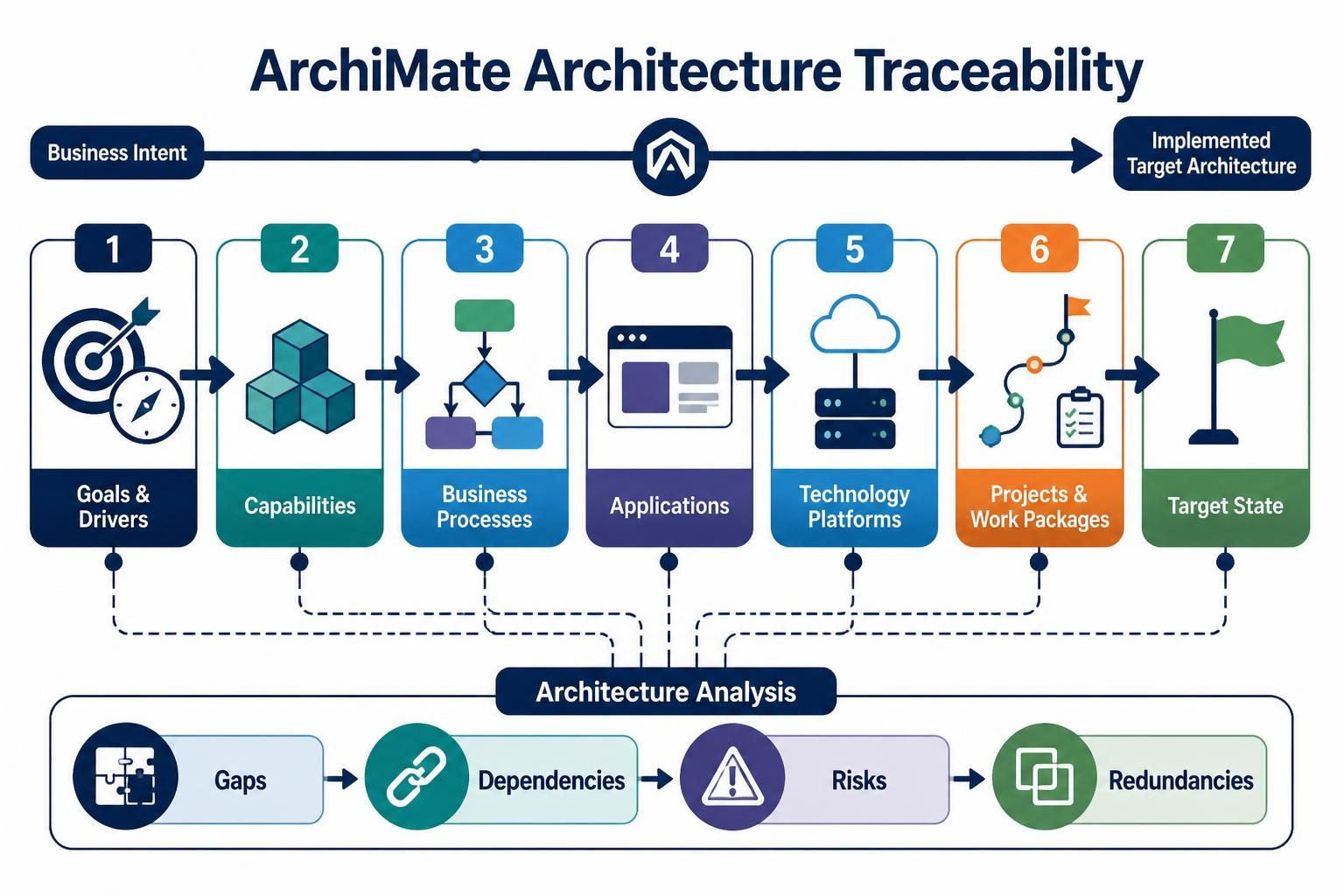
ArchiMate helps answer questions such as:
-
What business goals and drivers are shaping the architecture?
-
Which capabilities support those goals?
-
Which business processes deliver the required services?
-
Which applications support those processes?
-
Which technology platforms host those applications?
-
What projects or work packages will implement the target state?
-
Where are the gaps, dependencies, risks, and redundancies?
A useful model traces a chain such as:
Driver
  → Goal
    → Capability
      → Business Process
        → Application Service
          → Application Component
            → Technology Service
              → Node or System Software
ArchiMate is not intended to describe every implementation detail. It provides an architectural abstraction that connects strategy, business operations, information, applications, infrastructure, and change.
2. The main ArchiMate concepts
2.1 Layers
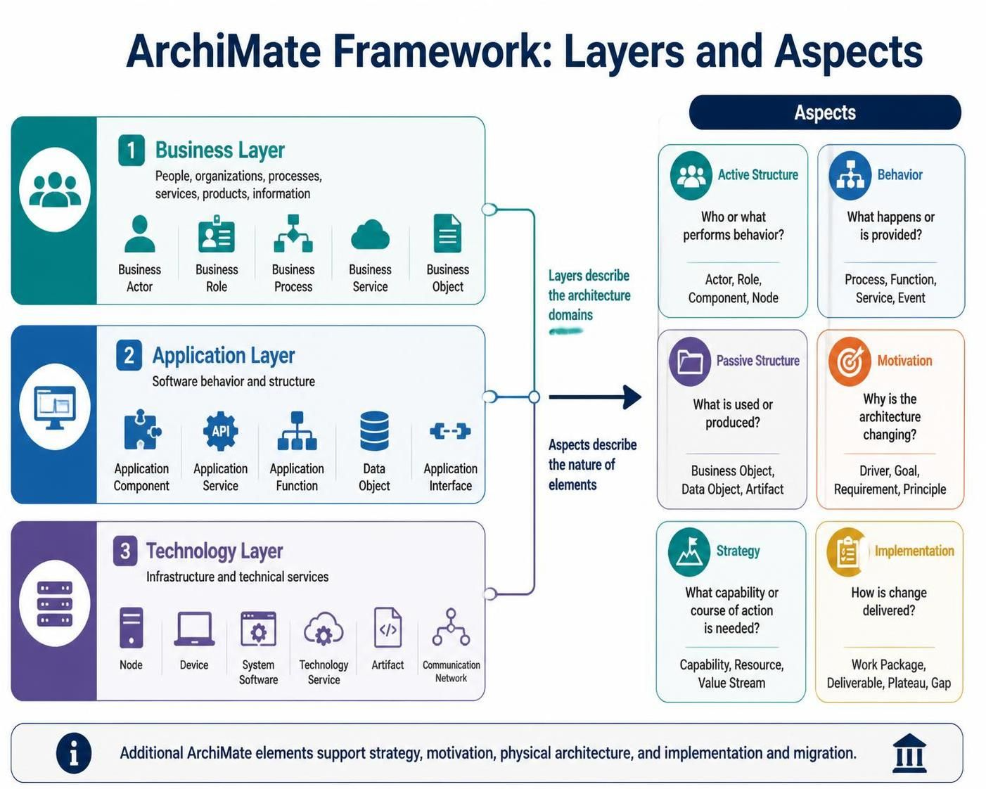
The classic ArchiMate structure uses three core layers.
| Layer | Describes | Typical elements |
|---|---|---|
| Business | People, organizations, processes, services, products, information | Business Actor, Business Role, Business Process, Business Service, Business Object |
| Application | Software behavior and structure | Application Component, Application Service, Application Function, Data Object, Application Interface |
| Technology | Infrastructure and technical services | Node, Device, System Software, Technology Service, Artifact, Communication Network |
Additional ArchiMate elements support strategy, motivation, physical architecture, and implementation and migration.
2.2 Aspect
Elements can also be understood by aspect:
| Aspect | Main question | Examples |
|---|---|---|
| Active structure | Who or what performs behavior? | Actor, Role, Component, Node |
| Behavior | What happens or is provided? | Process, Function, Service, Event |
| Passive structure | What is used or produced? | Business Object, Data Object, Artifact |
| Motivation | Why is the architecture changing? | Driver, Goal, Requirement, Principle |
| Strategy | What capability or course of action is needed? | Capability, Resource, Value Stream |
| Implementation | How is change delivered? | Work Package, Deliverable, Plateau, Gap |
The layer answers where an element belongs. The aspect answers what kind of thing it is.
For example:
-
Business Process: business layer + behavior aspect
-
Application Component: application layer + active structure
-
Data Object: application layer + passive structure
-
Capability: strategy aspect
-
Goal: motivation aspect
3. Frequently used ArchiMate elements
Motivation
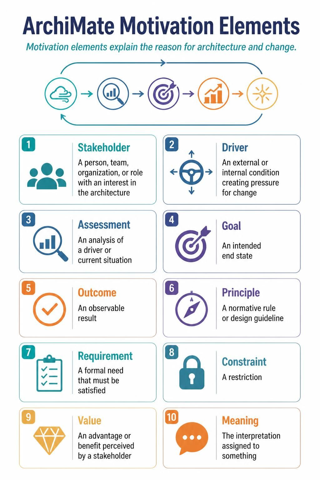
Motivation elements explain the reason for architecture and change.
-
Stakeholder — a person, team, organization, or role with an interest in the architecture
-
Driver — an external or internal condition creating pressure for change
-
Assessment — an analysis of a driver or current situation
-
Goal — an intended end state
-
Outcome — an observable result
-
Principle — a normative rule or design guideline
-
Requirement — a formal need that must be satisfied
-
Constraint — a restriction
-
Value — an advantage or benefit perceived by a stakeholder
-
Meaning — the interpretation assigned to something
Strategy
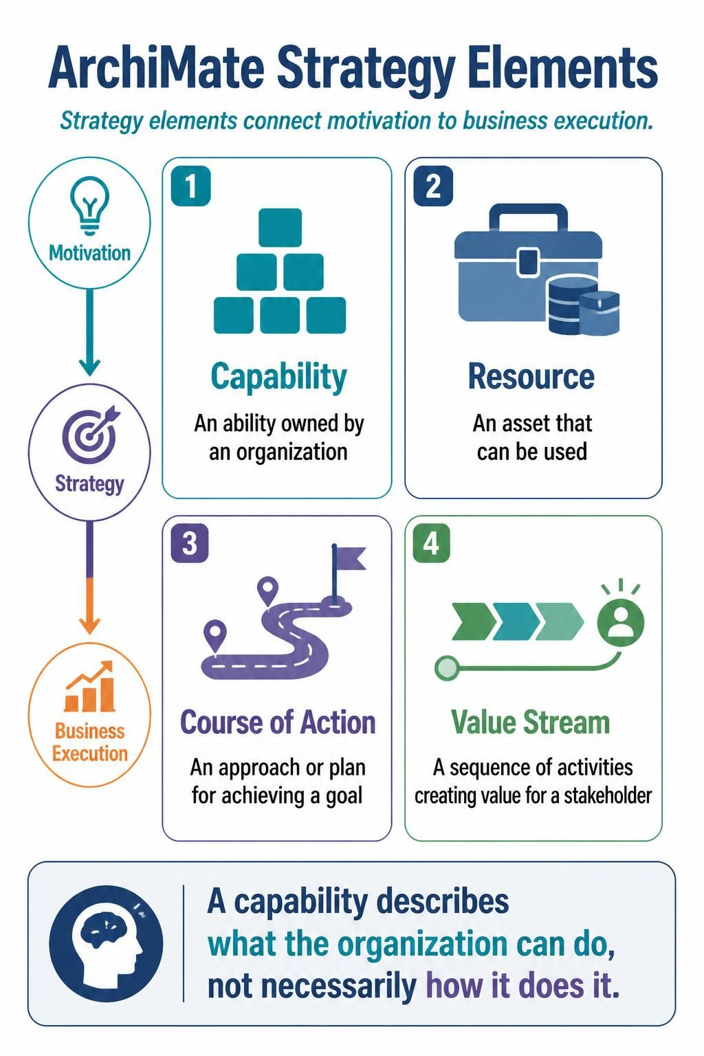
Strategy elements connect motivation to business execution.
-
Capability — an ability owned by an organization
-
Resource — an asset that can be used
-
Course of Action — an approach or plan for achieving a goal
-
Value Stream — a sequence of activities creating value for a stakeholder
A capability describes what the organization can do, not necessarily how it does it.
Business
Application
-
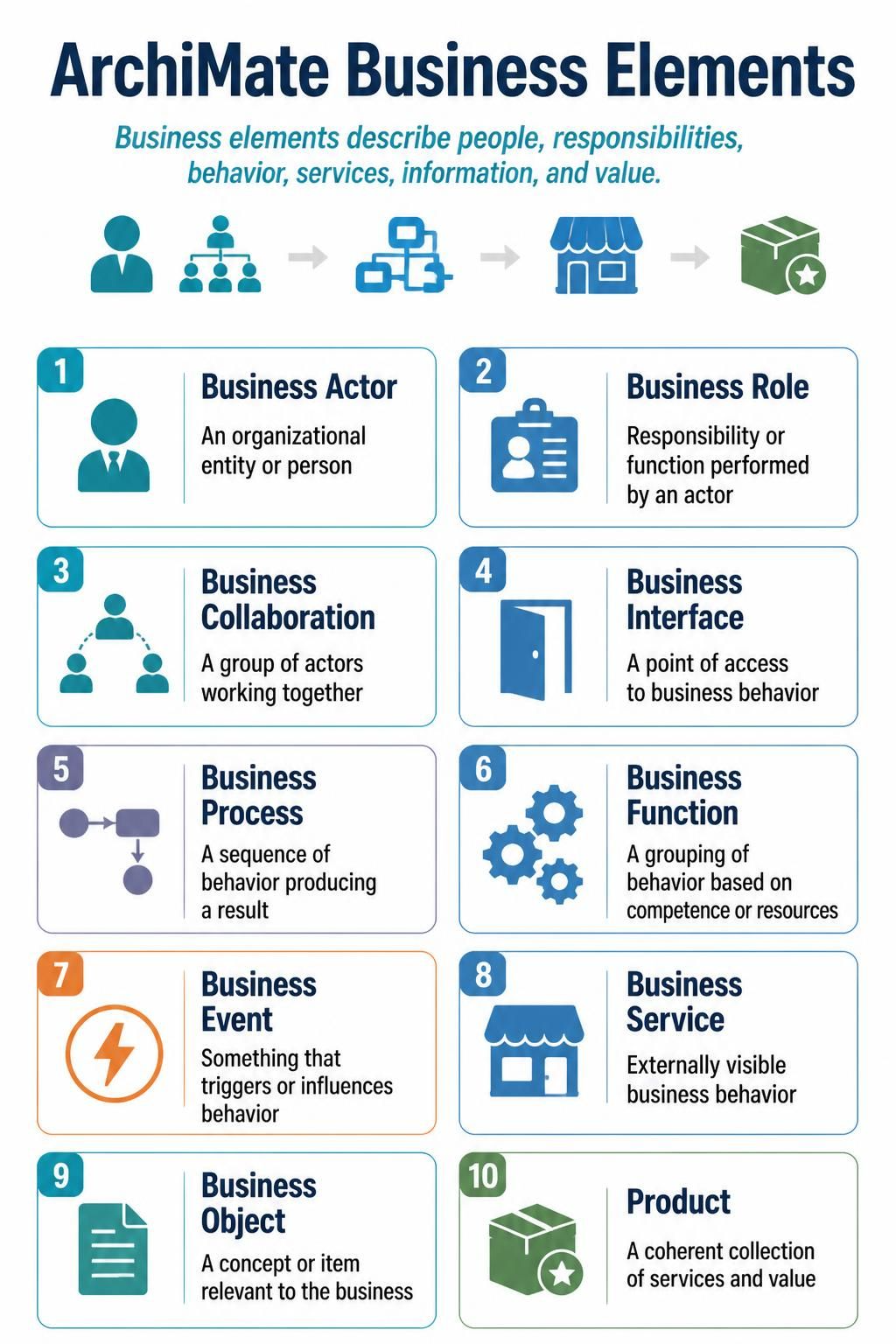
Business Actor — an organizational entity or person
-
Business Role — responsibility or function performed by an actor
-
Business Collaboration — a group of actors working together
-
Business Interface — a point of access to business behavior
-
Business Process — a sequence of behavior producing a result
-
Business Function — a grouping of behavior based on competence or resources
-
Business Event — something that triggers or influences behavior
-
Business Service — externally visible business behavior
-
Business Object — a concept or item relevant to the business
-
Product — a coherent collection of services and value
-
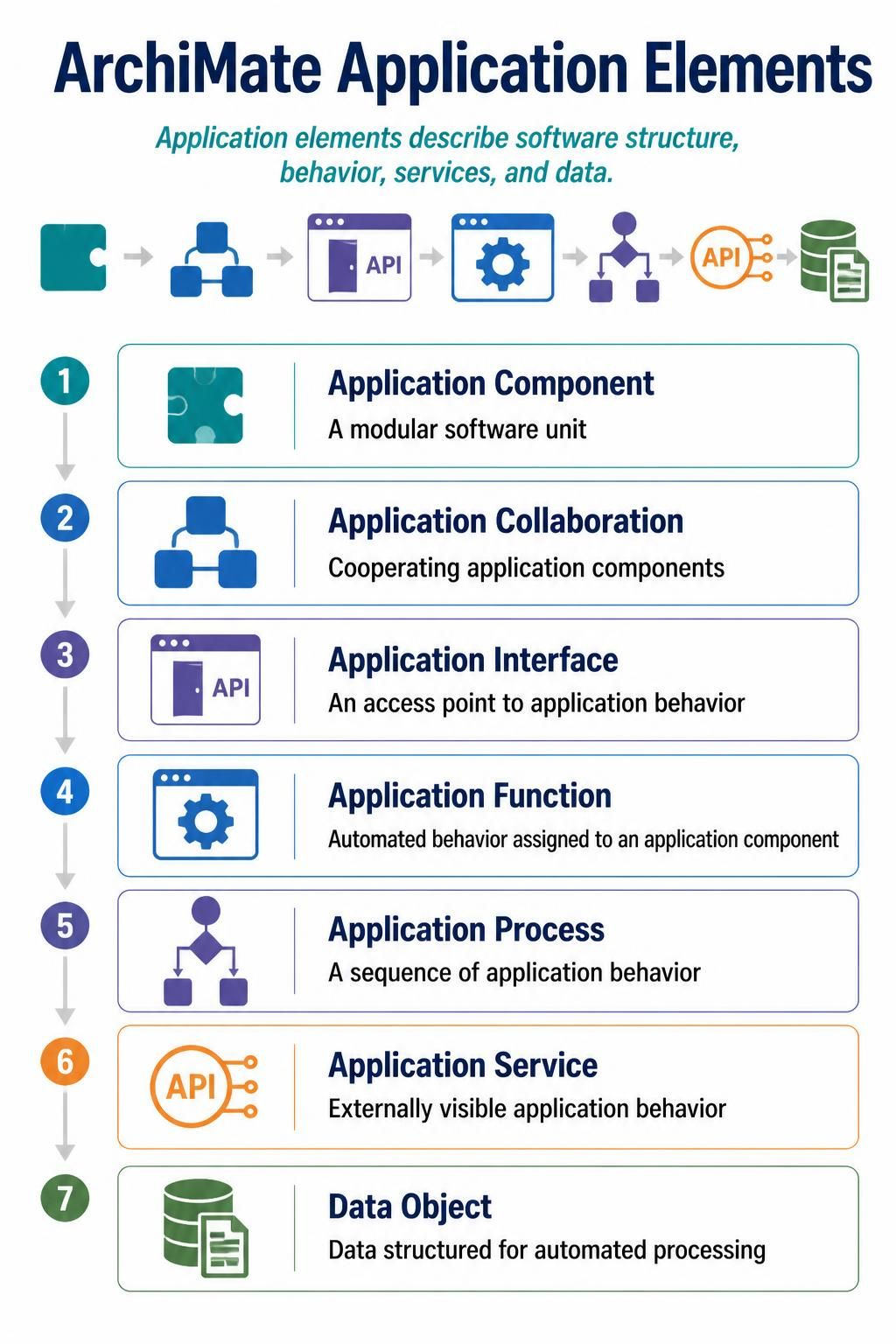
Application Component — a modular software unit
-
Application Collaboration — cooperating application components
-
Application Interface — an access point to application behavior
-
Application Function — automated behavior assigned to an application component
-
Application Process — a sequence of application behavior
-
Application Service — externally visible application behavior
-
Data Object — data structured for automated processing
Technology
-
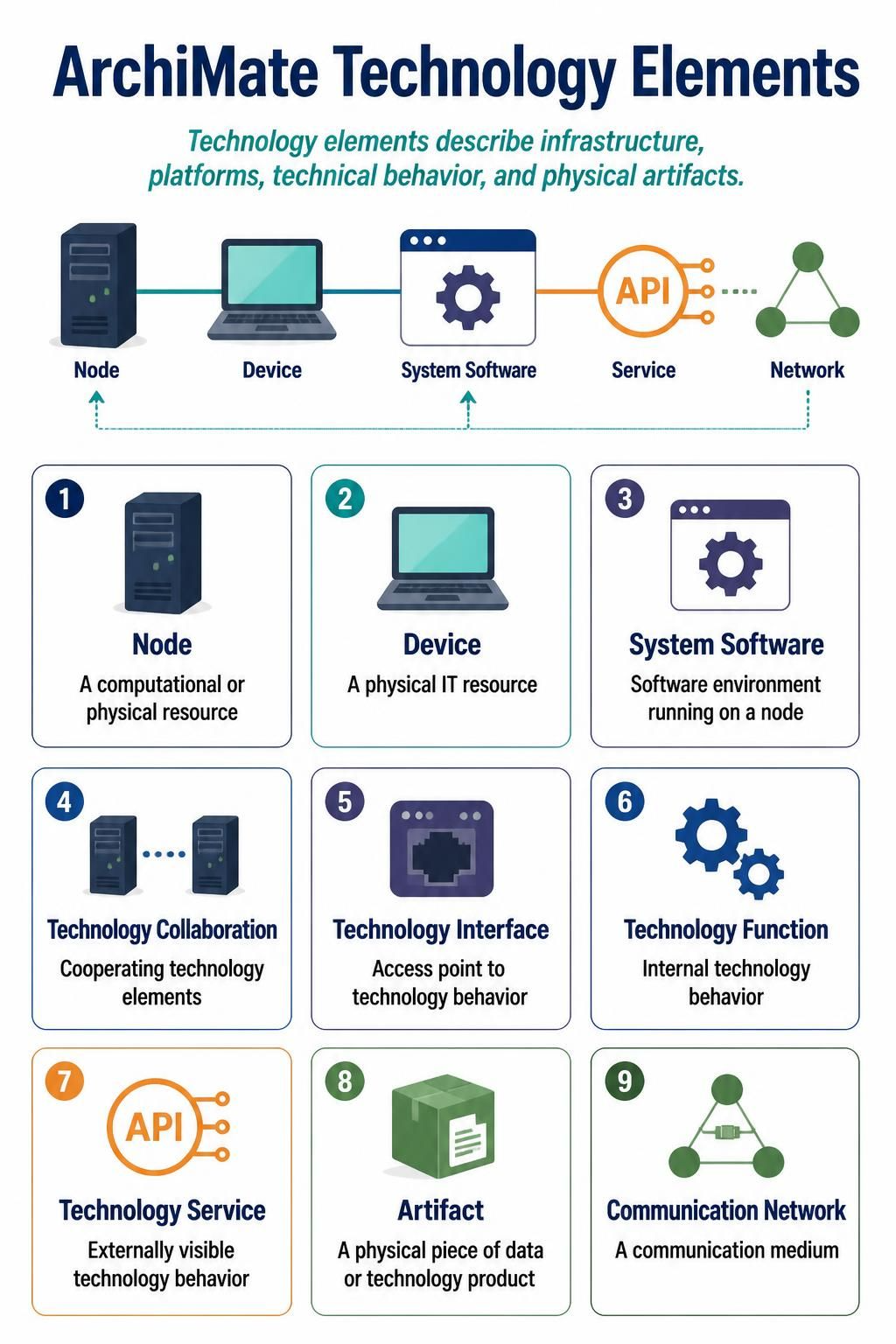
Node — a computational or physical resource
-
Device — a physical IT resource
-
System Software — software environment running on a node
-
Technology Collaboration — cooperating technology elements
-
Technology Interface — access point to technology behavior
-
Technology Function — internal technology behavior
-
Technology Service — externally visible technology behavior
-
Artifact — a physical piece of data or technology product
-
Communication Network — a communication medium
Implementation and migration
-
Work Package — a set of work performed to achieve a result
-
Deliverable — a precisely defined implementation result
-
Implementation Event — a state-changing event
-
Plateau — a relatively stable architectural state
-
Gap — a difference between two plateaus or architecture states
4. ArchiMate relationships
The official PlantUML library supports relationships including access, aggregation, assignment, association, composition, flow, influence, realization, serving, specialization, and triggering. Directional variants such as _Up, _Down, _Left, and _Right can help control the layout.
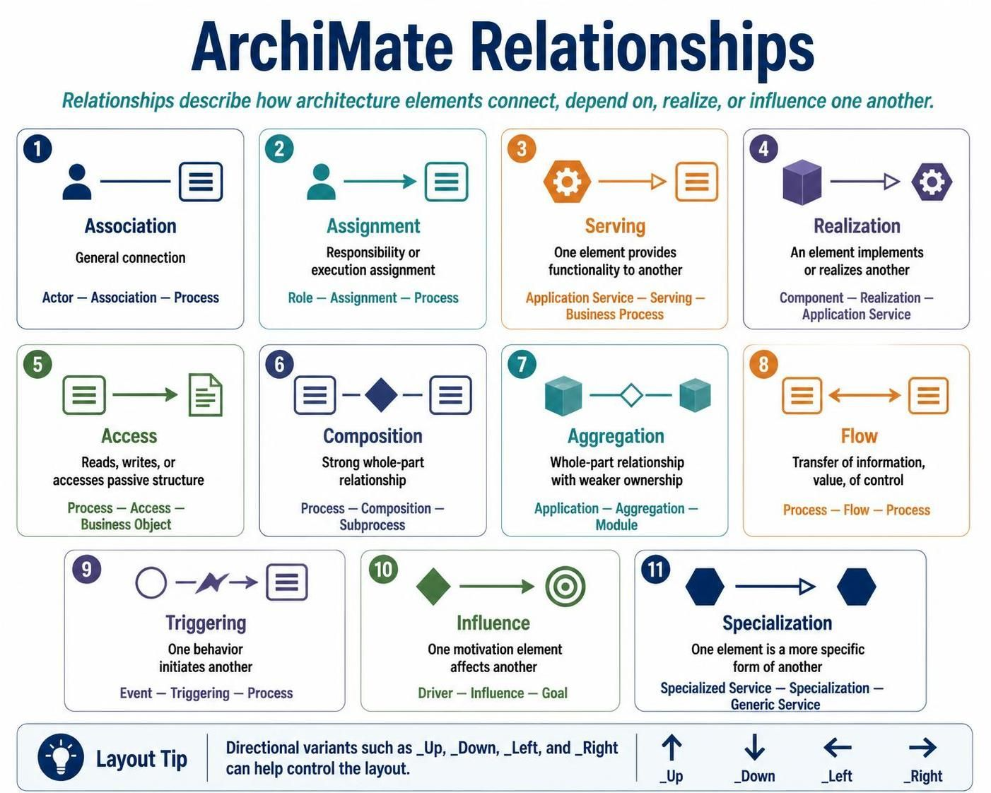
| Relationship | Meaning | Typical example |
|---|---|---|
| Association | General connection | Actor — Association — Process |
| Assignment | Responsibility or execution assignment | Role — Assignment — Process |
| Serving | One element provides functionality to another | Application Service — Serving — Business Process |
| Realization | An element implements or realizes another | Component — Realization — Application Service |
| Access | Reads, writes, or accesses passive structure | Process — Access — Business Object |
| Composition | Strong whole-part relationship | Process — Composition — Subprocess |
| Aggregation | Whole-part relationship with weaker ownership | Application — Aggregation — Module |
| Flow | Transfer of information, value, or control | Process — Flow — Process |
| Triggering | One behavior initiates another | Event — Triggering — Process |
| Influence | One motivation element affects another | Driver — Influence — Goal |
| Specialization | One element is a more specific form of another | Specialized Service — Specialization — Generic Service |
Access variants include:
Rel_Access(...)
Rel_Access_r(...)
Rel_Access_rw(...)
Rel_Access_w(...)
The suffixes represent read, write, and read-write access.
5. Installing and including ArchiMate-PlantUML
Option A: Use PlantUML’s built-in standard library
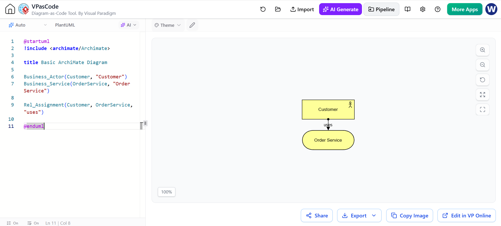
@startuml
!include <archimate/Archimate>

title Basic ArchiMate Diagram

Business_Actor(Customer, "Customer")
Business_Service(OrderService, "Order Service")

Rel_Assignment(Customer, OrderService, "uses")

@enduml
The project documentation recommends built-in support when the available PlantUML distribution already contains the ArchiMate library. It also documents a local-library approach for pinning a specific version.
Option B: Use a local copy
For reproducible builds, keep the library in your repository and include it explicitly:
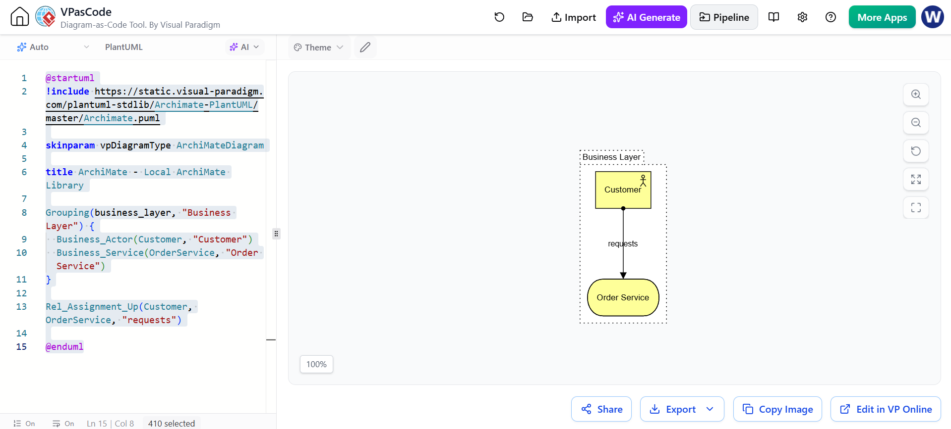
@startuml
!include https://static.visual-paradigm.com/plantuml-stdlib/Archimate-PlantUML/master/Archimate.puml

skinparam vpDiagramType ArchiMateDiagram

title ArchiMate - Local ArchiMate Library

Grouping(business_layer, "Business Layer") {
  Business_Actor(Customer, "Customer")
  Business_Service(OrderService, "Order Service")
}

Rel_Assignment_Up(Customer, OrderService, "requests")

@enduml
A local copy is useful when:
-
diagrams are rendered in CI/CD;
-
multiple team members need identical output;
-
you want to avoid changes caused by library updates;
-
diagrams must remain reproducible over time.
6. Basic syntax
6.1 Declaring an element
The general macro pattern is:
Category_ElementName(identifier, "display label")
Examples:
Motivation_Stakeholder(Customer, "Customer")
Motivation_Goal(FasterCheckout, "Faster checkout")
Strategy_Capability(OrderManagement, "Order Management")
Business_Process(ProcessOrder, "Process Order")
Business_Service(OrderService, "Order Service")
Application_Component(OrderApp, "Order Management Application")
Application_DataObject(OrderData, "Order Data")
Technology_Service(DatabaseService, "Database Service")
The identifier is used internally in relationships. The quoted label is displayed in the diagram.
6.2 Declaring a relationship
Rel_RelationType(source, target, "label")
Example:
Rel_Serving(OrderService, ProcessOrder, "supports")
Rel_Realization(OrderApp, OrderService, "realizes")
Rel_Access(ProcessOrder, OrderData, "reads and writes")
Directional forms can be used when the default layout is not satisfactory:
Rel_Serving_Up(OrderService, ProcessOrder, "")
Rel_Realization_Left(OrderApp, OrderService, "")
Rel_Flow_Right(ProcessOrder, ConfirmOrder, "order status")
6.3 Groups
Use groups to visually separate layers, domains, viewpoints, or architecture states:
Grouping(business, "Business Layer") {
  Business_Process(ProcessOrder, "Process Order")
  Business_Service(OrderService, "Order Service")
}

Grouping(application, "Application Layer") {
  Application_Component(OrderApp, "Order Application")
}
The library supports Group, Grouping, and Other_Grouping constructs.
7. Diagram example: motivation and strategy
This diagram connects a stakeholder and driver to a goal, capability, and course of action.
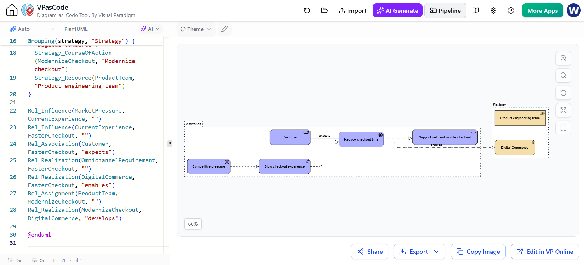
@startuml MotivationStrategy
!include <archimate/Archimate>

title Motivation and Strategy View

LAYOUT_LEFT_RIGHT()

Grouping(motivation, "Motivation") {
  Motivation_Stakeholder(Customer, "Customer")
  Motivation_Driver(MarketPressure, "Competitive pressure")
  Motivation_Assessment(CurrentExperience, "Slow checkout experience")
  Motivation_Goal(FasterCheckout, "Reduce checkout time")
  Motivation_Requirement(OmnichannelRequirement, "Support web and mobile checkout")
}

Grouping(strategy, "Strategy") {
  Strategy_Capability(DigitalCommerce, "Digital Commerce")
  Strategy_CourseOfAction(ModernizeCheckout, "Modernize checkout")
  Strategy_Resource(ProductTeam, "Product engineering team")
}

Rel_Influence(MarketPressure, CurrentExperience, "")
Rel_Influence(CurrentExperience, FasterCheckout, "")
Rel_Association(Customer, FasterCheckout, "expects")
Rel_Realization(OmnichannelRequirement, FasterCheckout, "")
Rel_Realization(DigitalCommerce, FasterCheckout, "enables")
Rel_Assignment(ProductTeam, ModernizeCheckout, "")
Rel_Realization(ModernizeCheckout, DigitalCommerce, "develops")

@enduml
Modeling interpretation
-
The market pressure creates an assessment.
-
The assessment identifies a poor customer experience.
-
The organization establishes a goal to reduce checkout time.
-
The capability represents the organizational ability required.
-
The course of action describes a strategic response.
-
The product team is a resource assigned to that course of action.
Avoid using a capability as if it were a project. A capability is a relatively enduring ability; a course of action or work package is usually temporary.
8. Diagram example: business process view
This example models order processing from a business perspective.
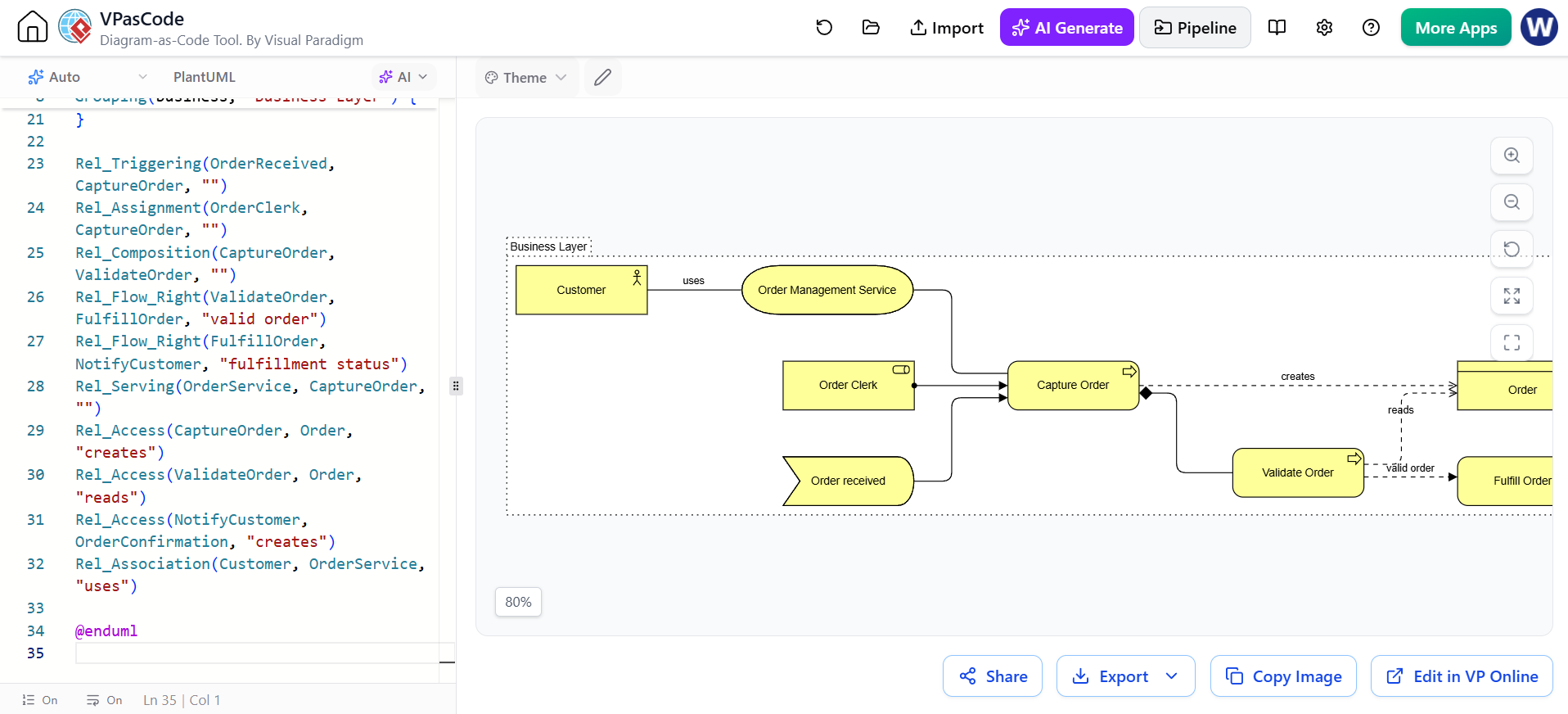
@startuml BusinessOrderProcess
!include <archimate/Archimate>

title Business Layer - Order Processing

LAYOUT_LEFT_RIGHT()

Grouping(business, "Business Layer") {
  Business_Actor(Customer, "Customer")
  Business_Role(OrderClerk, "Order Clerk")

  Business_Event(OrderReceived, "Order received")
  Business_Process(CaptureOrder, "Capture Order")
  Business_Process(ValidateOrder, "Validate Order")
  Business_Process(FulfillOrder, "Fulfill Order")
  Business_Process(NotifyCustomer, "Notify Customer")

  Business_Service(OrderService, "Order Management Service")
  Business_Object(Order, "Order")
  Business_Object(OrderConfirmation, "Order Confirmation")
}

Rel_Triggering(OrderReceived, CaptureOrder, "")
Rel_Assignment(OrderClerk, CaptureOrder, "")
Rel_Composition(CaptureOrder, ValidateOrder, "")
Rel_Flow_Right(ValidateOrder, FulfillOrder, "valid order")
Rel_Flow_Right(FulfillOrder, NotifyCustomer, "fulfillment status")
Rel_Serving(OrderService, CaptureOrder, "")
Rel_Access(CaptureOrder, Order, "creates")
Rel_Access(ValidateOrder, Order, "reads")
Rel_Access(NotifyCustomer, OrderConfirmation, "creates")
Rel_Association(Customer, OrderService, "uses")

@enduml

Modeling interpretation
The business service is the externally meaningful offering. The internal processes explain how the organization provides that service. The business object represents information meaningful to the business, not necessarily a database table.
9. Diagram example: application usage
This viewpoint shows how business behavior uses application services and components.
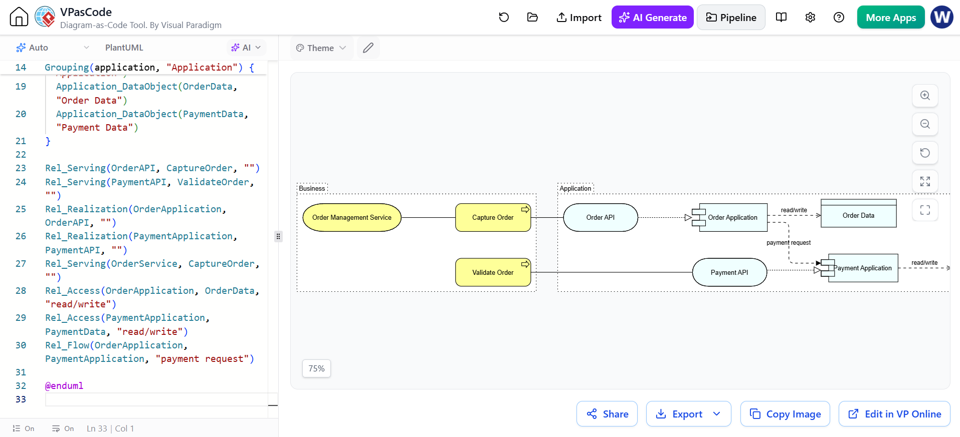
@startuml ApplicationUsage
!include <archimate/Archimate>

title Application Usage View

LAYOUT_LEFT_RIGHT()

Grouping(business, "Business") {
  Business_Process(CaptureOrder, "Capture Order")
  Business_Process(ValidateOrder, "Validate Order")
  Business_Service(OrderService, "Order Management Service")
}

Grouping(application, "Application") {
  Application_Service(OrderAPI, "Order API")
  Application_Service(PaymentAPI, "Payment API")
  Application_Component(OrderApplication, "Order Application")
  Application_Component(PaymentApplication, "Payment Application")
  Application_DataObject(OrderData, "Order Data")
  Application_DataObject(PaymentData, "Payment Data")
}

Rel_Serving(OrderAPI, CaptureOrder, "")
Rel_Serving(PaymentAPI, ValidateOrder, "")
Rel_Realization(OrderApplication, OrderAPI, "")
Rel_Realization(PaymentApplication, PaymentAPI, "")
Rel_Serving(OrderService, CaptureOrder, "")
Rel_Access(OrderApplication, OrderData, "read/write")
Rel_Access(PaymentApplication, PaymentData, "read/write")
Rel_Flow(OrderApplication, PaymentApplication, "payment request")

@enduml

Modeling interpretation
-
A business process consumes or uses application behavior.
-
An application service is the externally visible functionality.
-
An application component realizes or provides the application service.
-
A data object represents application-managed information.
Do not connect every application component to every business process. Show only meaningful architectural dependencies.
10. Diagram example: technology realization
This diagram maps application components to technology services and infrastructure.
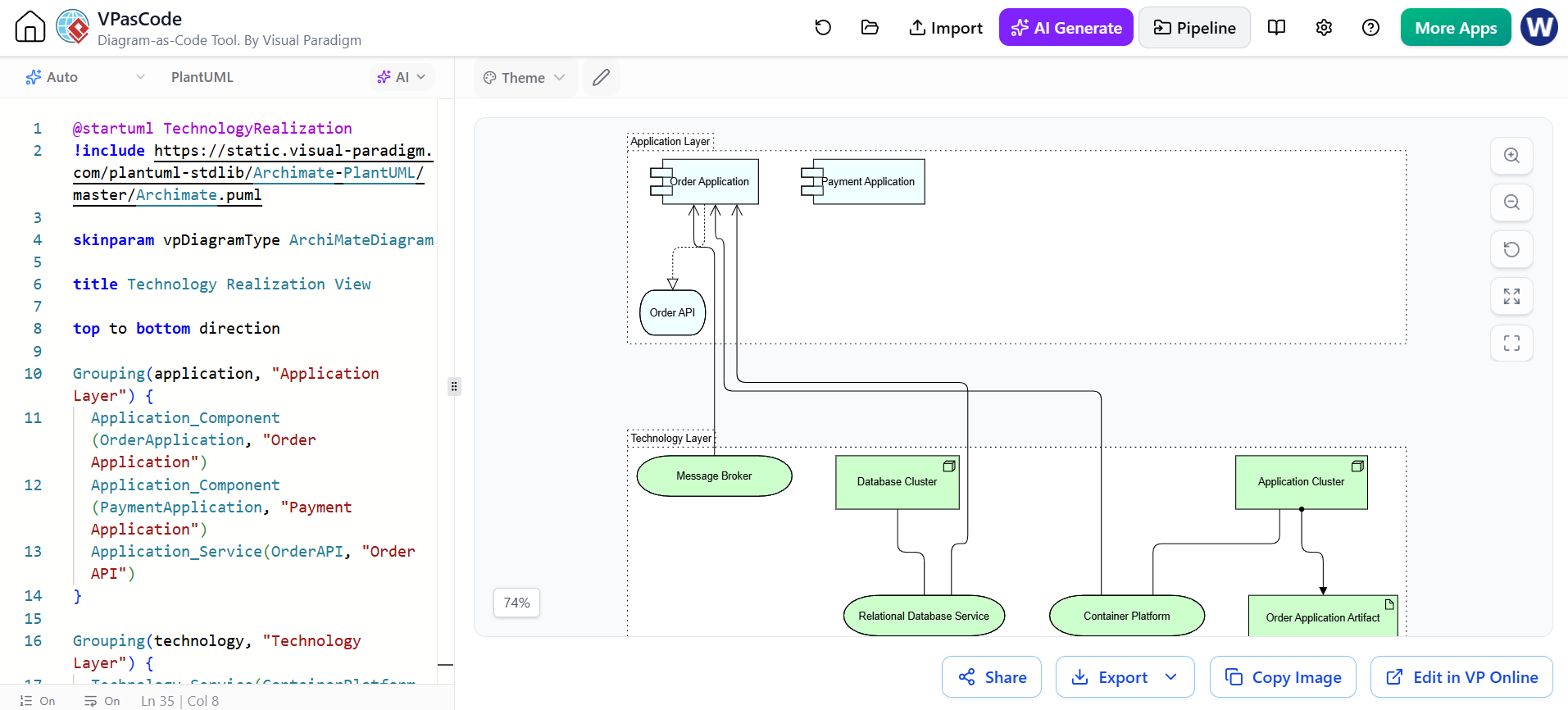
@startuml TechnologyRealization
!include https://static.visual-paradigm.com/plantuml-stdlib/Archimate-PlantUML/master/Archimate.puml

skinparam vpDiagramType ArchiMateDiagram

title Technology Realization View

top to bottom direction

Grouping(application, "Application Layer") {
  Application_Component(OrderApplication, "Order Application")
  Application_Component(PaymentApplication, "Payment Application")
  Application_Service(OrderAPI, "Order API")
}

Grouping(technology, "Technology Layer") {
  Technology_Service(ContainerPlatform, "Container Platform")
  Technology_Service(DatabaseService, "Relational Database Service")
  Technology_Service(MessageService, "Message Broker")

  Technology_Node(AppCluster, "Application Cluster")
  Technology_Node(DatabaseCluster, "Database Cluster")
  Technology_Artifact(OrderArtifact, "Order Application Artifact")
}

Rel_Realization_Up(OrderApplication, OrderAPI, "")
Rel_Serving_Up(ContainerPlatform, OrderApplication, "")
Rel_Serving_Up(DatabaseService, OrderApplication, "")
Rel_Serving_Up(MessageService, OrderApplication, "")

Rel_Assignment_Up(AppCluster, OrderArtifact, "")
Rel_Association(AppCluster, ContainerPlatform, "")
Rel_Association(DatabaseCluster, DatabaseService, "")

@enduml
Depending on the version of the ArchiMate-PlantUML library, a deployment-specific relationship such as Rel_Deployment may not be available as a standard macro. If it does not render, replace it with a supported relationship such as:
Rel_Association(OrderArtifact, AppCluster, "deployed on")
or:
Rel_Serving(ContainerPlatform, OrderApplication, "hosts")
The exact supported macro set should be checked against the version of Archimate.puml being used.
11. Diagram example: layered end-to-end architecture
This is a compact architecture map connecting business, application, and technology.
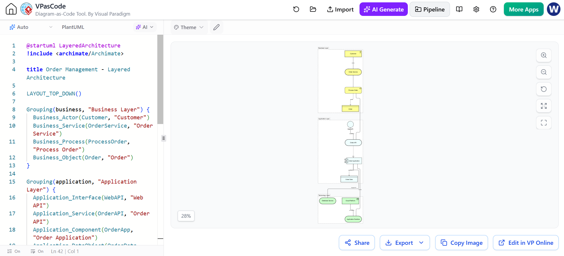
@startuml LayeredArchitecture
!include <archimate/Archimate>

title Order Management - Layered Architecture

LAYOUT_TOP_DOWN()

Grouping(business, "Business Layer") {
  Business_Actor(Customer, "Customer")
  Business_Service(OrderService, "Order Service")
  Business_Process(ProcessOrder, "Process Order")
  Business_Object(Order, "Order")
}

Grouping(application, "Application Layer") {
  Application_Interface(WebAPI, "Web API")
  Application_Service(OrderAPI, "Order API")
  Application_Component(OrderApp, "Order Application")
  Application_DataObject(OrderData, "Order Data")
}

Grouping(technology, "Technology Layer") {
  Technology_Service(Runtime, "Application Runtime")
  Technology_Service(Database, "Database Service")
  Technology_Node(CloudNode, "Cloud Platform")
}

Rel_Association(Customer, OrderService, "uses")
Rel_Serving(OrderService, ProcessOrder, "")
Rel_Access(ProcessOrder, Order, "uses")

Rel_Serving(OrderAPI, ProcessOrder, "")
Rel_Realization(OrderApp, OrderAPI, "")
Rel_Association(WebAPI, OrderAPI, "exposes")
Rel_Access(OrderApp, OrderData, "read/write")

Rel_Serving(Runtime, OrderApp, "hosts")
Rel_Serving(Database, OrderApp, "supports")
Rel_Association(CloudNode, Runtime, "provides")

@enduml
This type of diagram is useful for:
-
application portfolio discussions;
-
impact analysis;
-
architecture review boards;
-
modernization planning;
-
explaining dependencies to nontechnical stakeholders.
Keep it at an appropriate level. If every database table, API method, cloud resource, and process step is included, the diagram becomes an implementation diagram rather than an architecture view.
12. Diagram example: implementation and migration
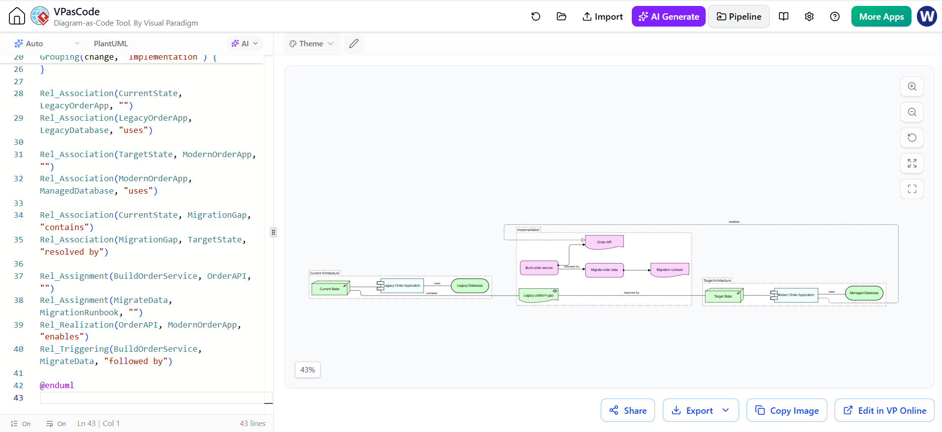
@startuml ImplementationMigration
!include <archimate/Archimate>

title Order Platform Migration

LAYOUT_LEFT_RIGHT()

Grouping(current, "Current Architecture") {
  Implementation_Plateau(CurrentState, "Current State")
  Application_Component(LegacyOrderApp, "Legacy Order Application")
  Technology_Service(LegacyDatabase, "Legacy Database")
}

Grouping(target, "Target Architecture") {
  Implementation_Plateau(TargetState, "Target State")
  Application_Component(ModernOrderApp, "Modern Order Application")
  Technology_Service(ManagedDatabase, "Managed Database")
}

Grouping(change, "Implementation") {
  Implementation_Gap(MigrationGap, "Legacy platform gap")
  Implementation_WorkPackage(BuildOrderService, "Build order service")
  Implementation_WorkPackage(MigrateData, "Migrate order data")
  Implementation_Deliverable(OrderAPI, "Order API")
  Implementation_Deliverable(MigrationRunbook, "Migration runbook")
}

Rel_Association(CurrentState, LegacyOrderApp, "")
Rel_Association(LegacyOrderApp, LegacyDatabase, "uses")

Rel_Association(TargetState, ModernOrderApp, "")
Rel_Association(ModernOrderApp, ManagedDatabase, "uses")

Rel_Association(CurrentState, MigrationGap, "contains")
Rel_Association(MigrationGap, TargetState, "resolved by")

Rel_Assignment(BuildOrderService, OrderAPI, "")
Rel_Assignment(MigrateData, MigrationRunbook, "")
Rel_Realization(OrderAPI, ModernOrderApp, "enables")
Rel_Triggering(BuildOrderService, MigrateData, "followed by")

@enduml
Modeling interpretation
-
Current State and Target State are plateaus.
-
The gap expresses the difference between them.
-
Work packages describe planned change.
-
Deliverables are concrete outputs of those work packages.
-
The target architecture should be connected to business goals and capabilities elsewhere in the repository.
13. Layout and readability
PlantUML uses Graphviz-style automatic layout. ArchiMate diagrams can become difficult to read when many relationships cross one another, so use layout controls deliberately.
Common helpers include:
LAYOUT_LEFT_RIGHT()
LAYOUT_TOP_DOWN()
LAYOUT_AS_SKETCH()
You can also add invisible links to influence layout:
Customer -[hidden]-> ProcessOrder
ProcessOrder -[hidden]-> OrderApp
OrderApp -[hidden]-> Runtime
Other useful techniques:
' Keep two elements close
OrderApp -[hidden]-- OrderAPI

' Increase separation
OrderApp -[hidden]---- Database

' Force a directional relationship
Rel_Serving_Up(OrderAPI, ProcessOrder, "")
Prefer several focused viewpoints over one enormous diagram. For example:
-
Motivation view
-
Capability map
-
Business process view
-
Application usage view
-
Technology view
-
Implementation roadmap
14. Styling and themes
The library supports ArchiMate themes, including standard and alternative visual styles. The project documentation shows theme declarations such as:
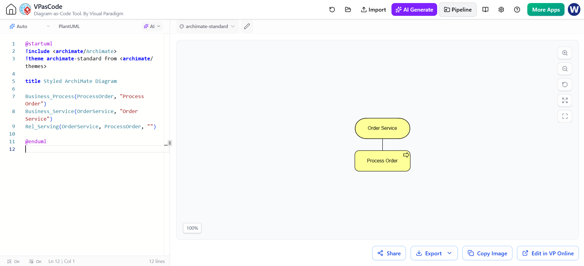
@startuml
!include <archimate/Archimate>
!theme archimate-standard from <archimate/themes>

title Styled ArchiMate Diagram

Business_Process(ProcessOrder, "Process Order")
Business_Service(OrderService, "Order Service")
Rel_Serving(OrderService, ProcessOrder, "")

@enduml
Other documented theme names include:
!theme archimate-alternate from <archimate/themes>
!theme archimate-handwriting from <archimate/themes>
!theme archimate-lowsaturation from <archimate/themes>
!theme archimate-saturated from <archimate/themes>
Use a consistent theme across a repository. Styling should clarify the architecture rather than compensate for unclear modeling.
15. Using sprites and legends
Sprites can make legends and documentation more recognizable.
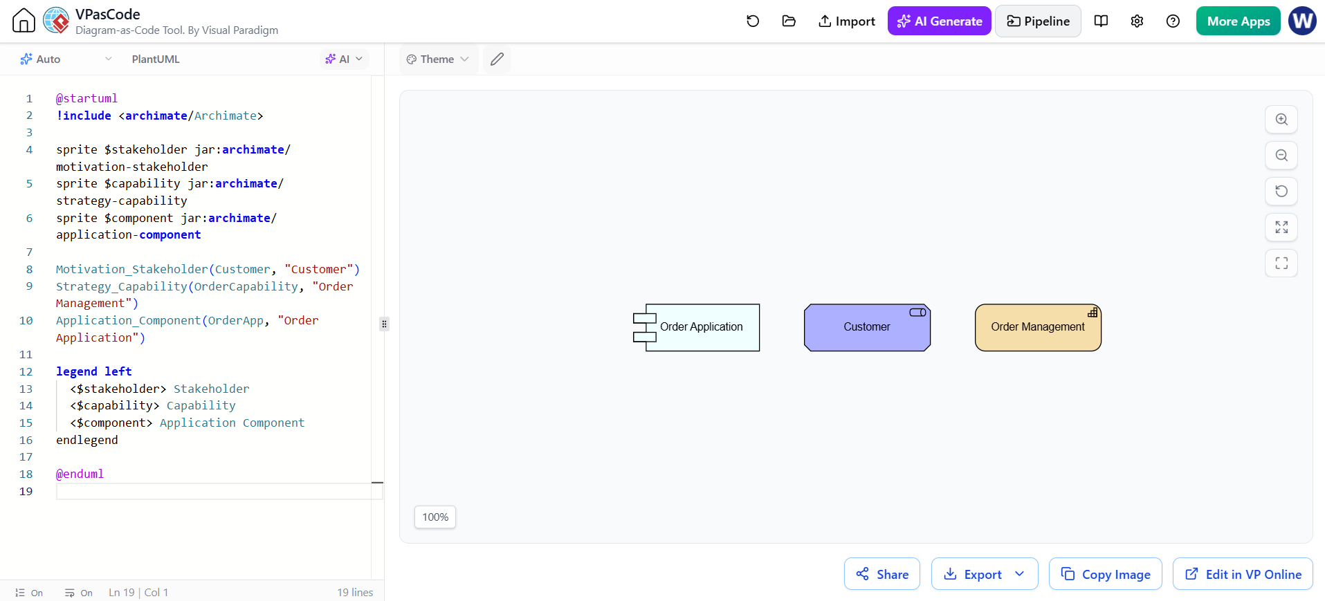
@startuml
!include <archimate/Archimate>

sprite $stakeholder jar:archimate/motivation-stakeholder
sprite $capability jar:archimate/strategy-capability
sprite $component jar:archimate/application-component

Motivation_Stakeholder(Customer, "Customer")
Strategy_Capability(OrderCapability, "Order Management")
Application_Component(OrderApp, "Order Application")

legend left
  <$stakeholder> Stakeholder
  <$capability> Capability
  <$component> Application Component
endlegend

@enduml
A legend is especially useful when diagrams are consumed by people who do not work with ArchiMate every day.
16. Using Visual Paradigm
Visual Paradigm is useful when the model requires:
-
a formal repository of elements and relationships;
-
stakeholder-specific viewpoints;
-
traceability between diagrams;
-
documentation and publishing;
-
model navigation and impact analysis;
-
collaboration with analysts and architects who prefer visual editing.
A practical workflow is:
-
Establish the architecture vocabulary in Visual Paradigm.
-
Define canonical names for capabilities, services, applications, and technology platforms.
-
Create stakeholder-oriented viewpoints.
-
Use VPasCode and PlantUML for rapidly iterated or version-controlled diagrams.
-
Reconcile important diagrams with the formal model.
-
Publish approved diagrams and documentation from the governed source.
Visual Paradigm’s ArchiMate guidance emphasizes viewpoints as subsets of the language tailored to particular stakeholders, such as business process cooperation, application usage, technology deployment, and strategy views.
Suggested division of responsibility
| Activity | Best-fit tool |
|---|---|
| Enterprise repository and governed model | Visual Paradigm |
| Formal viewpoint management | Visual Paradigm |
| Rapid diagram prototyping | VPasCode |
| Code review and version control | PlantUML files in Git |
| Generating first drafts | AI chatbot |
| Reviewing semantics and consistency | AI chatbot plus architect |
| Final stakeholder presentation | Visual Paradigm or exported PlantUML diagrams |
Do not treat separately created diagrams as automatically synchronized. Establish one authoritative source for element names, IDs, and approved relationships.
17. Using VPasCode
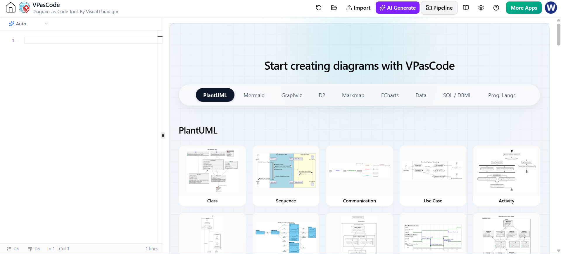
VPasCode is a browser-based text-to-diagram environment with a code editor and live renderer. Its documented support includes PlantUML and ArchiMate, and it can preview diagrams as the code is edited.
A basic VPasCode workflow is:
-
Open the PlantUML editor.
-
Start with:
PlantUML Edit PlantUML in VPasCode@startuml !include <archimate/Archimate> @enduml -
Add one or two elements.
-
Add relationships.
-
Use the live preview to correct syntax and layout.
-
Add groups for layers or viewpoints.
-
Export or copy the source into the project repository.
-
Review the generated model with an architect.
VPasCode also documents native AI diagram generation and the ability to edit generated diagrams in the VPasCode editor.
For team work, keep the final .puml source in Git even if VPasCode was used to create it.
18. Using an AI chatbot effectively
An AI chatbot is most useful as a modeling assistant, not as the authority for architecture decisions.
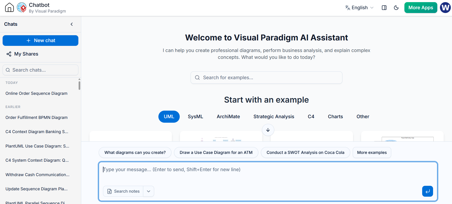
Good uses
-
Convert a written scenario into candidate ArchiMate elements.
-
Generate an initial PlantUML diagram.
-
Explain an existing diagram.
-
Find invalid or questionable relationships.
-
Suggest a viewpoint for a stakeholder group.
-
Split an overloaded diagram into smaller views.
-
Normalize naming.
-
Generate documentation from the model.
-
Compare current and target architectures.
-
Identify missing traceability from goals to implementation.
Strong prompt template
Create an ArchiMate-PlantUML diagram for the following scenario.

Scenario:
A customer places an order through a web channel. The order service validates
the order, requests payment authorization, and sends the order to fulfillment.

Requirements:
- Use the official ArchiMate-PlantUML macro syntax.
- Include business, application, and technology elements.
- Group elements by layer.
- Use only supported ArchiMate relationships.
- Use stable identifiers with readable display labels.
- Add directional relationship variants where useful.
- Return only compilable PlantUML inside one code block.
- Explain any modeling assumptions after the code.
Review prompt
Review this ArchiMate-PlantUML code.

Check:
1. Whether each macro is a valid ArchiMate-PlantUML element.
2. Whether the relationships are semantically appropriate.
3. Whether layer and aspect classifications are reasonable.
4. Whether any element is overloaded or ambiguous.
5. Whether the diagram should be split into multiple viewpoints.
6. Whether the code is likely to render with the included library.

Return:
- errors,
- semantic concerns,
- layout suggestions,
- corrected PlantUML.
AI-generated code should be checked for
-
invented macro names;
-
invalid relationships;
-
confusing identifier and label usage;
-
treating capabilities as applications;
-
treating services as internal implementation components;
-
mixing business objects with database tables;
-
excessive use of association;
-
inaccurate direction labels;
-
duplicated elements with slightly different names;
-
unsupported deployment or relationship macros.
19. Recommended repository structure
A simple project structure might be:
architecture/
├── README.md
├── conventions.md
├── glossary.md
├── plantuml/
│   ├── lib/
│   │   └── archimate/
│   │       ├── Archimate.puml
│   │       └── themes/
│   ├── motivation/
│   │   └── digital-commerce.puml
│   ├── business/
│   │   └── order-process.puml
│   ├── application/
│   │   └── application-usage.puml
│   ├── technology/
│   │   └── deployment.puml
│   └── implementation/
│       └── migration-roadmap.puml
├── generated/
│   ├── motivation/
│   ├── business/
│   ├── application/
│   └── technology/
└── scripts/
    └── render-diagrams.sh
A reusable file header can standardize diagrams:
@startuml
!global $ARCH_LOCAL = %true()
!include ../lib/archimate/Archimate.puml
!theme archimate-standard from ../lib/archimate/themes

title Order Management - Application Usage
hide stereotype
skinparam shadowing false

LAYOUT_LEFT_RIGHT()
20. Naming conventions
Use stable identifiers and human-readable labels separately:
Application_Component(orderManagementApplication, "Order Management Application")
Recommended conventions:
-
Use PascalCase or camelCase for identifiers.
-
Use business language in display labels.
-
Avoid abbreviations unless they are widely understood.
-
Use one canonical name for each architecture element.
-
Avoid names such as
System1,ServiceA, orComponentX. -
Distinguish similar concepts with context:
-
OrderBusinessService -
OrderApplicationService -
OrderTechnologyService
-
-
Keep labels short enough to fit in a node.
-
Put details in documentation rather than excessively long labels.
A glossary file should define terms such as “customer,” “order,” “account,” “product,” “case,” and “service” before modeling begins.
21. Common modeling mistakes
Modeling every detail
An architecture diagram should not become a complete inventory of classes, tables, endpoints, and servers. Use a lower-level UML, data, or deployment diagram when implementation detail is needed.
Confusing service and component
A service is externally visible behavior. A component is a structural element that may provide or realize that behavior.
Application Component → realizes → Application Service
Using association for everything
Association is a generic connection, but it communicates less meaning than serving, realization, access, flow, assignment, or triggering. Use the most specific relationship that accurately describes the dependency.
Treating a goal as a requirement
A goal expresses an intended result. A requirement is a condition that must be met. A goal such as “Improve customer experience” may lead to requirements such as “Checkout must support guest users.”
Treating a capability as a process
A capability is an ability. A process is a sequence of behavior. For example:
Capability: Order Management
Process: Validate Order
Mixing abstraction levels
Avoid placing a high-level business capability beside dozens of low-level infrastructure artifacts unless the viewpoint has a clear purpose.
Overusing directional suffixes
Directional suffixes help layout; they do not change the semantic meaning of a relationship. The source and target still need to be correct.
Assuming generated code is valid
AI-generated PlantUML can contain plausible but unsupported macros. Render the code and compare its relationships against the library’s supported syntax.
22. A practical modeling method
Use this sequence for a new architecture problem:
-
Define the scope
Choose an organization, product, value stream, initiative, or platform. -
Identify stakeholders
Determine who needs to understand or approve the architecture. -
Choose a viewpoint
Do not start with a blank canvas. Choose motivation, strategy, business, application usage, technology, or implementation. -
Capture the motivation
Model drivers, assessments, goals, principles, and requirements. -
Model capabilities
Describe what the organization must be able to do. -
Model business behavior
Add actors, roles, processes, services, and business objects. -
Map applications
Identify application services, components, interfaces, and data objects. -
Map technology
Add technology services, nodes, devices, system software, and artifacts only where relevant. -
Model change
Add plateaus, gaps, work packages, deliverables, and implementation events. -
Validate traceability
Check that important goals connect to capabilities, business behavior, applications, and implementation. -
Review with stakeholders
Confirm that the model is understandable and useful to its intended audience. -
Publish and maintain
Store source files, rendered diagrams, decisions, and glossary terms together.
23. Validation checklist
Before publishing an ArchiMate diagram, check:
Semantic quality
-
Does every element have a clear meaning?
-
Are element types appropriate?
-
Are relationships more specific than generic association where possible?
-
Are business, application, and technology concerns separated clearly?
-
Are capabilities distinguished from processes and projects?
Traceability
-
Can important goals be traced to capabilities?
-
Can capabilities be traced to business services or processes?
-
Can business behavior be traced to application services?
-
Can application components be traced to technology services?
-
Can gaps be traced to work packages and deliverables?
Diagram quality
-
Is the viewpoint clear?
-
Is the diagram readable at normal zoom?
-
Are labels concise?
-
Are relationships crossing unnecessarily?
-
Would splitting the diagram improve comprehension?
-
Is a legend needed?
Technical quality
-
Does the PlantUML source render?
-
Is the ArchiMate library version controlled?
-
Are macro names supported by that version?
-
Are generated images reproducible?
-
Are identifiers stable across diagrams?
Final recommended workflow
Use Visual Paradigm as the governed architecture modeling environment, VPasCode as the rapid PlantUML editing and preview environment, and an AI chatbot as a drafting and review assistant.
A strong end-to-end process is:
Business question
  → AI-assisted modeling draft
    → VPasCode live rendering
      → semantic review
        → Visual Paradigm governance and viewpoints
          → Git versioning
            → automated rendering and publication
The most important discipline is to treat the diagram source as a model rather than as decoration. Use precise ArchiMate concepts, meaningful relationships, stable names, focused viewpoints, and explicit traceability from motivation through implementation.
Related posts:
 Revolutionizing Enterprise Architecture in 2026: Visual Paradigm’s Generative AI for ArchiMate
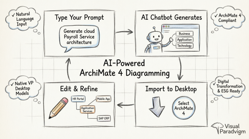 How to Generate and Import ArchiMate 4 Diagrams Using Visual Paradigm’s AI Chatbot
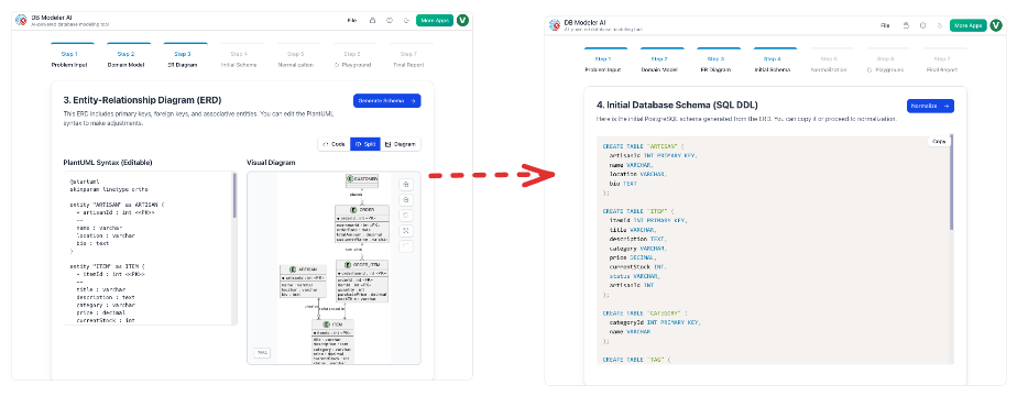 From Static Diagrams to Living Knowledge: A Case Study on Visual Paradigm’s Unified AI-Driven Documentation Ecosystem
Comprehensive Guide to Custom AI Endpoint Support in Visual Paradigm
From Static Diagrams to Living Knowledge: A Case Study on Visual Paradigm’s Unified AI-Driven Documentation Ecosystem
Comprehensive Guide to Custom AI Endpoint Support in Visual Paradigm

 English
 Arabic
 Chinese (Simplified)
 Dutch
Dutch French
 German
 Italian
 Japanese
 Korean
 Portuguese
 Russian
 Spanish