


1. Introduction
Business Process Model and Notation, or BPMN, is a standardized visual language for describing how business work is performed. It shows activities, events, decisions, responsibilities, data, and communication between participants.
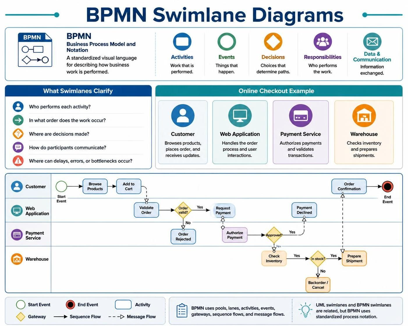
A swimlane diagram organizes process activities according to the people, departments, systems, or organizations responsible for performing them. This makes it easier to answer:
-
Who performs each activity?
-
In what order does the work occur?
-
Where are decisions made?
-
How do participants communicate?
-
Where can delays, errors, or bottlenecks occur?
The example used in this guide is an online checkout process involving:
-
A customer
-
A web application
-
A payment service
-
A warehouse
The original example resembles a UML swimlane activity diagram. In BPMN, the same process is modeled using pools, lanes, activities, events, gateways, sequence flows, and message flows.
2. The Online Checkout Example
The process begins when a customer decides to purchase a product. The customer browses products, adds an item to a cart, and starts checkout. The web application validates the order and sends a payment request to a payment service.
If the payment is rejected, the customer is notified and the process ends or returns to payment correction. If payment is approved, the warehouse checks inventory. If the product is unavailable, the customer receives an out-of-stock notification. If the product is available, the warehouse prepares the shipment and the web application sends a confirmation to the customer.
A simplified process sequence is:
-
Customer browses products.
-
Web application displays product details.
-
Customer adds a product to the cart.
-
Customer begins checkout.
-
Web application validates the order.
-
The process checks whether the order is valid.
-
The payment service authorizes payment.
-
The process checks whether payment is approved.
-
The warehouse reserves inventory.
-
The process checks whether the item is in stock.
-
The warehouse prepares the shipment.
-
The customer receives an order confirmation.
3. UML Swimlanes and BPMN Swimlanes
UML activity diagrams and BPMN diagrams can both use swimlanes, but their notation and modeling purposes differ.
| Concept | UML Activity Diagram | BPMN |
|---|---|---|
| Main purpose | Describe system or behavioral activity flow | Describe business processes and organizational behavior |
| Responsibility areas | Activity partitions or swimlanes | Pools and lanes |
| Start symbol | Initial node | Start event |
| End symbol | Activity final node | End event |
| Decision | Decision node | Gateway |
| Flow between activities | Control flow | Sequence flow |
| Communication between participants | Often represented informally | Message flow |
| External participant | Usually a partition or actor | Pool |
| Business messages | Optional or less formal | Explicit message flow and message events |
The generated online-checkout image can therefore be treated as a conceptual starting point. For a formal BPMN model, use BPMN events and gateways rather than UML initial nodes, activity-final nodes, and decision nodes.
4. BPMN Swimlane Fundamentals
4.1 Pools
A pool represents a participant in a business process. A participant may be:
-
A customer
-
A company
-
A department
-
A supplier
-
A payment provider
-
An external application
-
A government agency
For the checkout example, suitable pools include:
-
Customer
-
Online Store
-
Payment Service
-
Warehouse
Pools are especially useful when the participants are separate organizations or independent systems. BPMN supports communication between pools using message flows.
A pool may be shown as a white-box pool containing process activities, or as a black-box pool that represents an external participant whose internal process is not modeled.
4.2 Lanes
A lane is a subdivision within a pool. Lanes organize activities by role, department, team, or system.
For example, instead of creating separate pools for every internal responsibility, the online store may use one pool containing several lanes:
Online Store pool
-
Web Application lane
-
Order Management lane
-
Customer Support lane
Lanes are appropriate when the participants belong to the same organization or process boundary. Visual Paradigm describes lanes as partitions within a pool that organize activities according to responsibility. Pools represent participants, while lanes categorize work inside a participant.
4.3 Choosing Pools and Lanes
Use a pool when:
-
The participant is an external organization.
-
The participant has its own independent process.
-
Communication occurs across organizational or system boundaries.
-
You want to hide the participant’s internal activities.
Use a lane when:
-
The role belongs to the same organization.
-
The division is internal.
-
The purpose is to assign responsibility.
-
Activities need to be grouped by department, role, or application component.
A common modeling error is to create a lane for every individual action. Lanes should represent stable responsibility categories, not temporary process steps.
5. BPMN Elements Used in the Example
5.1 Start Event
A start event indicates where the process begins.
For the online checkout process, the start event might be labeled:
Customer decides to purchase
The BPMN start event is drawn as a circle with a thin border.
5.2 Tasks and Activities
An activity represents work performed by a person, system, or organization. Activities are normally shown as rounded rectangles.
Examples include:
-
Browse products
-
Add item to cart
-
Validate order
-
Authorize payment
-
Reserve inventory
-
Prepare shipment
-
Send confirmation
Activities should be written using a verb followed by an object:
-
Validate order
-
Authorize payment
-
Reserve inventory
Avoid vague labels such as:
-
Processing
-
Checkout
-
Payment
-
Inventory
More precise labels improve understanding and support later process analysis.
5.3 Exclusive Gateway
An exclusive gateway represents a decision where only one outgoing path is selected.
Examples:
-
Order valid?
-
Payment approved?
-
Item in stock?
It is represented by a diamond, often containing an “X” marker or left unmarked depending on the modeling convention.
Outgoing sequence flows should use conditions such as:
-
[Yes] -
[No] -
[Approved] -
[Rejected] -
[In stock] -
[Out of stock]
5.4 Sequence Flow
A sequence flow is a solid line with an arrowhead. It represents the order in which activities occur inside the same process or pool. BPMN uses sequence flow to connect events, activities, and gateways.
Example:
Validate Order → Order Valid? → Request Payment
A sequence flow should generally not cross from one pool to another. When two separate pools communicate, use a message flow.
5.5 Message Flow
A message flow represents communication between separate pools. It is normally shown using a dashed line with an open arrowhead.
Examples include:
-
Web application sends payment request to payment service.
-
Payment service sends authorization result to web application.
-
Web application sends fulfillment request to warehouse.
-
Web application sends order confirmation to customer.
Message flows represent the exchange of information, not the internal order of work.
5.6 End Event
An end event indicates that a process path has completed.
Possible end events in this example include:
-
Payment failed
-
Product unavailable
-
Order confirmed
-
Shipment prepared
A process may have multiple end events if different outcomes need to be shown explicitly.
6. Recommended BPMN Structure for the Example
A practical BPMN representation can use four pools:
| Pool | Responsibility |
|---|---|
| Customer | Selects products, begins checkout, receives confirmation |
| Online Store | Validates orders, coordinates payment and fulfillment |
| Payment Service | Authorizes or rejects payment |
| Warehouse | Checks inventory and prepares shipment |
An alternative design uses one Online Store pool with lanes:
| Pool | Lane |
|---|---|
| Customer | Customer |
| Online Store | Web Application |
| Online Store | Order Management |
| Online Store | Fulfillment |
| Payment Service | Payment Processing |
| Warehouse | Warehouse Operations |
The first design emphasizes independent participants. The second design emphasizes internal responsibilities within the online-store organization.
7. BPMN Process Flow
The process can be described as follows.
7.1 Customer Interaction
The customer begins the process by browsing the online store. The web application displays product information. The customer selects an item and adds it to the cart.
The main activities are:
Start
→ Browse Products
→ Display Product Details
→ Add Item to Cart
→ Display Cart
→ Start Checkout
The customer’s activities belong in the Customer pool or Customer lane. The display activities belong in the Web Application lane.
7.2 Order Validation
After checkout begins, the web application validates:
-
Product availability information
-
Customer identity
-
Delivery address
-
Required order fields
-
Cart contents
-
Pricing and taxes
The process then reaches the gateway:
Order valid?
If the answer is no, the application displays an error. The customer may correct the cart or checkout details. This can be modeled as a loop:
Order Valid?
 ├── [No] → Display Validation Error → Edit Cart → Validate Order
 └── [Yes] → Request Payment
A loop should be used only when the customer genuinely has the opportunity to correct the problem and retry.
7.3 Payment Authorization
The web application sends a payment request to the payment service. This is a message flow between the Online Store pool and the Payment Service pool.
The payment service performs the authorization task:
Authorize Payment
The result is returned to the web application. The next gateway asks:
Payment approved?
If payment is rejected, the application displays a failure message. The customer may choose another payment method or cancel the order.
If payment is approved, the store sends a fulfillment request to the warehouse.
7.4 Inventory and Fulfillment
The warehouse receives the fulfillment request and checks inventory.
The process then reaches the gateway:
Item in stock?
If the item is unavailable:
Item Out of Stock
→ Notify Customer
→ End
If the item is available:
Reserve Inventory
→ Prepare Shipment
→ Send Fulfillment Result
The web application then sends an order confirmation to the customer.
8. Example BPMN Text Specification
The following specification can be used as a blueprint when creating the diagram:
Pool: Customer
  Start Event: Customer begins shopping
  Task: Browse products
  Task: Add item to cart
  Task: Start checkout
  Task: Edit cart
  Intermediate Message Event: Receive order confirmation
  End Event: Customer receives confirmation

Pool: Online Store
  Lane: Web Application
    Task: Display product details
    Task: Display cart
    Task: Validate order
    Gateway: Order valid?
    Task: Display validation error
    Task: Request payment
    Task: Display payment failure
    Task: Confirm order
    Task: Notify customer of unavailable item

  Lane: Order Management
    Task: Create order
    Task: Send fulfillment request

Pool: Payment Service
  Start or Message Catch Event: Receive payment request
  Task: Authorize payment
  Gateway: Payment approved?
  Message Throw Event: Return payment result

Pool: Warehouse
  Message Catch Event: Receive fulfillment request
  Task: Check inventory
  Gateway: Item in stock?
  Task: Reserve inventory
  Task: Prepare shipment
  Message Throw Event: Send fulfillment result
This structure separates:
-
Internal sequence flow within a participant
-
External message flow between participants
-
Responsibility for each activity
-
Alternative outcomes
-
Successful and unsuccessful end states
9. Modeling the Example in Visual Paradigm
Visual Paradigm provides BPMN modeling tools for creating business process diagrams, pools, lanes, activities, gateways, events, connectors, and annotations. Its BPMN tutorials demonstrate creating a Business Process Diagram, adding pools, adding lanes, inserting lanes after existing lanes, resizing lanes, and creating child lanes.
9.1 Create a BPMN Project
-
Open Visual Paradigm.
-
Create a new project.
-
Select the option for creating a new diagram.
-
Choose Business Process Diagram.
-
Give the diagram a descriptive name, such as:
Online Checkout Process
Use a project name that reflects the process rather than the software system alone.
9.2 Add the Customer Pool
-
Select the horizontal pool tool.
-
Click on the diagram canvas.
-
Name the pool:
Customer
The Customer pool should contain activities directly performed by the customer.
9.3 Add the Online Store Pool
-
Add a second pool below or beside the Customer pool.
-
Name it:
Online Store
-
Add lanes inside it, such as:
Web Application
Order Management
If warehouse activities are performed by the same company, add a Warehouse lane inside this pool instead of creating a separate Warehouse pool.
9.4 Add the Payment Service Pool
Create a separate pool named:
Payment Service
This is appropriate because the payment provider is an external participant. Its internal implementation does not need to be modeled unless it is part of the study.
9.5 Add the Warehouse Pool
Create a separate pool named:
Warehouse
Use a separate pool if the warehouse is operated by an independent logistics provider. If it is an internal department, model it as a lane inside the Online Store pool.
9.6 Add Events and Activities
From the BPMN palette, add:
-
A start event
-
User tasks for customer actions
-
Service tasks for automated web application actions
-
Service tasks for payment authorization
-
Manual or user tasks for warehouse work
-
End events for each major outcome
Suggested task types:
| Activity | Suggested BPMN type |
|---|---|
| Browse products | User Task |
| Add item to cart | User Task |
| Validate order | Service Task |
| Display cart | Service Task |
| Authorize payment | Service Task |
| Reserve inventory | Service Task |
| Prepare shipment | Manual Task or User Task |
| Send confirmation | Send Task or Service Task |
The exact task type depends on whether the work is performed by a person, an application, or an external service.
9.7 Add Gateways
Add exclusive gateways for:
-
Order valid?
-
Payment approved?
-
Item in stock?
Connect each gateway to its alternatives using sequence flows. Label the flows with conditions:
[Yes]
[No]
or:
[Approved]
[Rejected]
9.8 Connect Activities
Use sequence flows within each pool or lane.
For example:
Start Event
→ Browse Products
→ Add Item to Cart
→ Start Checkout
Within the Online Store:
Validate Order
→ Order Valid?
Use message flows between pools:
Online Store ─ ─ ─ ─> Payment Service
Payment Service ─ ─ ─ ─> Online Store
Online Store ─ ─ ─ ─> Warehouse
Online Store ─ ─ ─ ─> Customer
Do not use sequence flow to connect separate independent pools.
9.9 Resize and Align Swimlanes
After adding elements:
-
Resize lanes so activities have sufficient space.
-
Align activities from left to right.
-
Keep the main successful path visually straightforward.
-
Place exception paths above or below the main flow.
-
Avoid excessive line crossings.
-
Keep gateway branches close to their corresponding decisions.
Visual Paradigm’s swimlane workflow includes resizing lanes and adding child lanes when additional levels of responsibility are needed.
9.10 Add Data Objects
Useful data objects for the checkout process include:
-
Product Catalog
-
Shopping Cart
-
Customer Order
-
Payment Request
-
Payment Result
-
Shipment Request
-
Order Confirmation
Data objects should be connected to activities with associations rather than sequence flows. For example:
Validate Order → Customer Order
Authorize Payment → Payment Request
Prepare Shipment → Shipment Request
Confirm Order → Order Confirmation
Data objects describe information used or created by the process. They do not represent the order of execution.
10. Tooling: Visual Paradigm BPMN
10.1 Visual Paradigm BPMN Capabilities
Visual Paradigm supports BPMN diagram creation through both desktop and browser-based tooling. The BPMN Online tool supports browser-based modeling, drag-and-drop diagram creation, and collaborative process documentation without requiring a desktop installation.
Important tooling capabilities include:
-
BPMN pools and lanes
-
BPMN events
-
Activities and task types
-
Gateways
-
Sequence flows
-
Message flows
-
Data objects
-
Annotations
-
Diagram formatting and alignment
-
Model documentation
-
Collaboration and sharing
-
Process simulation in suitable editions or environments
-
Export and publishing options
The available capabilities can depend on the Visual Paradigm edition and deployment environment.
10.2 Visual Paradigm Desktop
Visual Paradigm Desktop is appropriate when the model is part of a larger modeling project. It is useful for:
-
Maintaining multiple related diagrams
-
Creating formal model repositories
-
Linking business processes to other models
-
Creating documentation
-
Managing larger projects
-
Working offline
-
Performing deeper analysis and customization
The desktop environment is especially suitable for enterprise modeling teams that need a long-lived process model rather than a single diagram.
10.3 Visual Paradigm Online
Visual Paradigm Online is suitable for:
-
Quickly creating BPMN diagrams
-
Working in a browser
-
Sharing process models
-
Collaborating with stakeholders
-
Including diagrams in online documentation
-
Reviewing diagrams with distributed teams
A browser-based tool reduces installation requirements and can make process modeling more accessible to business users.
10.4 Diagram Toolbar and Palette
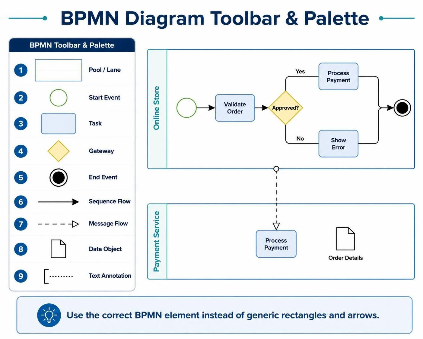
The BPMN palette provides access to the main diagram elements. A typical modeling workflow uses:
-
Pool or lane
-
Start event
-
Task
-
Gateway
-
End event
-
Sequence flow
-
Message flow
-
Data object
-
Text annotation
The modeler should select the correct BPMN element rather than approximating the notation with generic rectangles and arrows.
10.5 Resource Catalog and Connector Creation
Visual Paradigm supports diagramming workflows in which users create elements and connect them directly. A resource catalog or quick-connector mechanism can speed up modeling by allowing the user to create a connected next element without repeatedly returning to the palette.
This is useful when building the main process path:
Start Event → Task → Task → Gateway → Task
However, automatic connector creation should still be reviewed. The modeler must confirm that the connector is a sequence flow or message flow as appropriate.
10.6 Validation and Quality Review
A finished BPMN diagram should be inspected for:
-
Missing start events
-
Missing end events
-
Incorrect gateway connections
-
Sequence flows crossing pool boundaries
-
Message flows used inside a single pool
-
Activities placed in the wrong lane
-
Unlabeled gateway branches
-
Ambiguous task names
-
Unconnected elements
-
Excessive line crossings
-
Incorrect use of data associations
A modeling tool can help identify structural problems, but business stakeholders must still verify whether the process reflects reality.
10.7 Simulation and Analysis
Some Visual Paradigm environments support process simulation and analysis. A model can potentially be used to examine:
-
Processing time
-
Waiting time
-
Resource utilization
-
Queue length
-
Bottlenecks
-
Alternative paths
-
Completion rates
-
Cost or performance indicators
Simulation is meaningful only when the model includes sufficiently reliable assumptions about:
-
Task duration
-
Arrival rates
-
Resource availability
-
Gateway probabilities
-
Error rates
-
Working schedules
A visually correct diagram alone does not guarantee a meaningful simulation.
11. BPMN Modeling Best Practices
11.1 Use Clear Responsibility Boundaries
Every activity should belong to the participant or role responsible for performing it. If responsibility is unclear, the process model is incomplete.
Instead of:
Payment
use:
Authorize Payment
This makes the responsible participant and expected result clearer.
11.2 Use Consistent Direction
A left-to-right layout is usually effective for the main process. Activities should generally follow the process direction, while alternate paths can branch above or below.
Avoid forcing the reader to follow a line backward unless the process genuinely loops.
11.3 Keep Gateways Close to Decisions
Place the gateway immediately after the activity that produces the decision result.
Recommended:
Validate Order → Order Valid?
Avoid placing a gateway several steps away from the activity that determines its outcome.
11.4 Label Conditional Flows
Every outgoing branch from a decision gateway should be clear.
Good labels include:
[Yes]
[No]
[Approved]
[Rejected]
[In stock]
[Out of stock]
Unlabeled branches force the reader to infer the meaning.
11.5 Avoid Overloading One Diagram
A process diagram should communicate one coherent process at an appropriate level of detail. If the payment process becomes complex, create a separate subprocess diagram for payment authorization and link to it from the high-level model.
Possible decomposition:
-
Online Checkout
-
Payment Authorization
-
Inventory Fulfillment
-
Shipment and Delivery
-
Returns and Refunds
11.6 Separate Internal Work from Communication
The following are different concepts:
-
A task describes work.
-
A sequence flow describes order.
-
A message flow describes communication.
-
A data object describes information.
-
An annotation describes explanatory context.
Using one connector for all purposes reduces the clarity and correctness of the model.
11.7 Use Appropriate BPMN Task Types
Task types communicate implementation or responsibility:
-
User Task: performed by a person through an application
-
Manual Task: performed manually without system assistance
-
Service Task: performed automatically by a system or service
-
Send Task: sends a message
-
Receive Task: waits for a message
-
Script Task: executes a script
-
Business Rule Task: evaluates business rules
For example:
-
“Browse products” is commonly a User Task.
-
“Validate order” may be a Service Task.
-
“Authorize payment” may be a Service Task.
-
“Prepare shipment” may be a Manual Task or User Task.
Do not select specialized task types unless they add useful meaning.
12. Common Errors in Swimlane BPMN Diagrams
Error 1: Treating Every Participant as a Lane
An external payment provider should generally be modeled as a pool, not merely as a lane inside the online store.
Correction: Use a separate pool when the participant is independent or communicates through messages.
Error 2: Using Sequence Flow Between Pools
Sequence flow represents order inside a process. It should not be used to show communication between independent pools.
Correction: Use message flow between pools.
Error 3: Omitting End Events
A process path should have a meaningful conclusion.
Correction: Add end events for successful, rejected, cancelled, and exception outcomes where appropriate.
Error 4: Using Generic Activity Names
Labels such as “Process Payment” or “Handle Order” are too broad.
Correction: Use precise action-oriented names such as “Authorize Payment” and “Validate Order.”
Error 5: Unclear Gateway Logic
A diamond without labeled branches makes the process difficult to interpret.
Correction: Label outgoing flows with conditions.
Error 6: Confusing Data Flow and Sequence Flow
A document or order should not be connected with a sequence arrow merely because it is used by an activity.
Correction: Use a data association between the activity and data object.
Error 7: Excessive Detail
Including every database query, screen field, and internal API call can make the business process unreadable.
Correction: Keep the primary diagram at a business-process level and use subprocesses for technical detail.
Error 8: Mixing UML and BPMN Symbols
A UML activity final node is not the same as a BPMN end event. A UML decision node is not automatically a BPMN gateway.
Correction: Use BPMN-native symbols when producing a BPMN model.
13. Quality Checklist
Use the following checklist before publishing the diagram.
Structure
-
The process has a clear start event.
-
Major paths have end events.
-
Every activity belongs to a pool or lane.
-
Pools and lanes represent meaningful responsibilities.
-
The diagram has a consistent direction.
Flow
-
Sequence flows connect activities within a process.
-
Message flows connect separate participants.
-
Gateway branches are labeled.
-
Loops are understandable.
-
No unnecessary line crossings exist.
Semantics
-
Activities use verb-object names.
-
Gateways represent real process decisions.
-
Data objects represent information rather than activities.
-
Task types match the way work is performed.
-
External participants are modeled separately when appropriate.
Communication
-
Business stakeholders can understand the diagram.
-
Technical stakeholders can identify system responsibilities.
-
Exceptions and failure paths are visible.
-
Important assumptions are documented.
-
The diagram is not overloaded with unnecessary detail.
14. Suggested Final BPMN Layout
A clear layout for the online checkout example is:
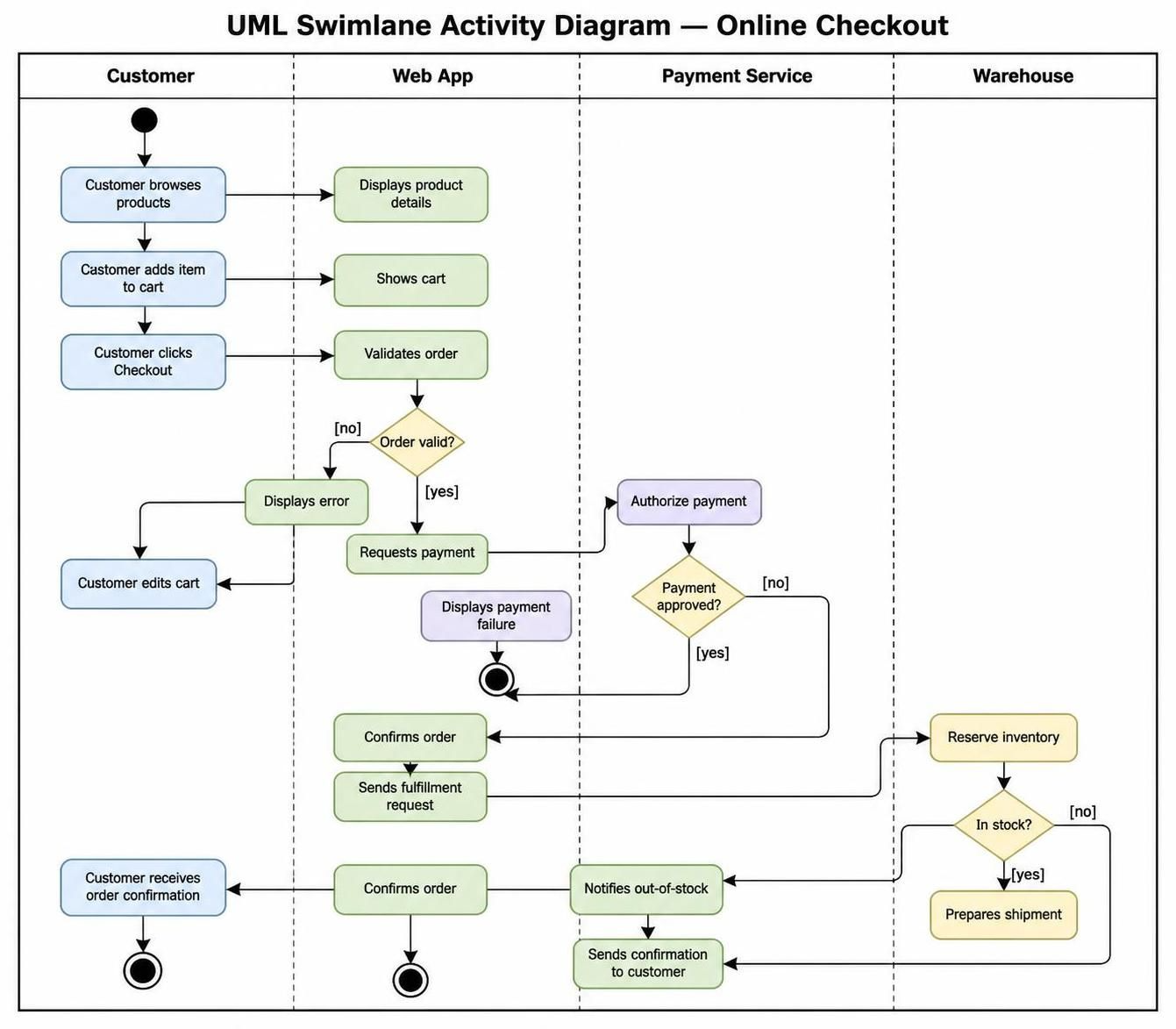
This layout preserves the conceptual structure of the original swimlane example while applying BPMN conventions for participants, responsibilities, messages, decisions, and completion states.
15. Conclusion
A swimlane BPMN diagram is most useful when it clearly combines three perspectives:
-
Process perspective: What activities occur and in what order?
-
Responsibility perspective: Who performs each activity?
-
Communication perspective: How do participants exchange information?
For the online checkout example, the key modeling decision is to distinguish internal responsibility from external participation. The customer, payment service, and warehouse may be represented as separate pools when they operate independently. The web application and order-management functions may be represented as lanes within the online-store pool.
Visual Paradigm provides the modeling environment needed to create these structures, add BPMN elements, connect flows, organize lanes, document data, and collaborate on process models. Its BPMN notation guidance confirms the core distinction between pools and lanes and the separate roles of sequence flow, message flow, and associations.
The strongest final model is not necessarily the most detailed one. It is the one that makes responsibilities, decisions, communication, and outcomes immediately understandable to both business and technical stakeholders.



 English
 Arabic
 Chinese (Simplified)
 Dutch
Dutch French
 German
 Italian
 Japanese
 Korean
 Portuguese
 Russian
 Spanish