


Introduction
In the rapidly evolving landscape of software development, Unified Modeling Language (UML) remains a vital tool for visualizing, specifying, and documenting complex systems. However, traditional modeling methods are often labor-intensive, frequently resulting in a disconnect between architectural models and final technical documentation. Models become outdated the moment they are created, leading to “documentation drift” that undermines their value.
To bridge this gap, a modern, AI-enhanced workflow has emerged. This guide explores a cohesive ecosystem centered on the powerful integration of Visual Paradigm’s desktop modeling, AI-driven generation, and the OpenDocs knowledge management platform. We will illustrate the journey from concept to living documentation, demonstrating how teams can leverage tools like PlantUML and VPasCode to create accurate, up-to-date, and accessible technical knowledge.
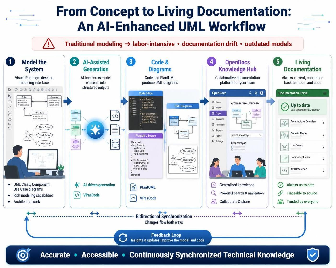
1. Key Concepts: The Modern UML Modeling Ecosystem
The traditional approach to UML often involves creating diagrams in isolation, exporting them as static images, and manually pasting them into Word documents or Wikis. This process is fragile and error-prone. The modern ecosystem revolves around four core pillars that ensure traceability and efficiency:
-
Visual Paradigm Desktop & Online: Professional modeling environments for creating precise, standard-compliant UML diagrams.
-
AI Visual Modeling Chatbot & Generators: Tools that generate diagrams from natural language prompts, instantly overcoming the “blank page” syndrome and accelerating initial design.
-
OpenDocs: An AI-powered, collaborative knowledge management platform where documentation and models coexist as a single source of truth. Unlike static wikis, diagrams embedded in OpenDocs remain live and interactive.
-
The Pipeline: A secure, cloud-based repository that acts as the bridge between all these tools, enabling a fluid “model-to-document” workflow. When a source model changes, OpenDocs flags the change, allowing you to update the documentation with a single click.
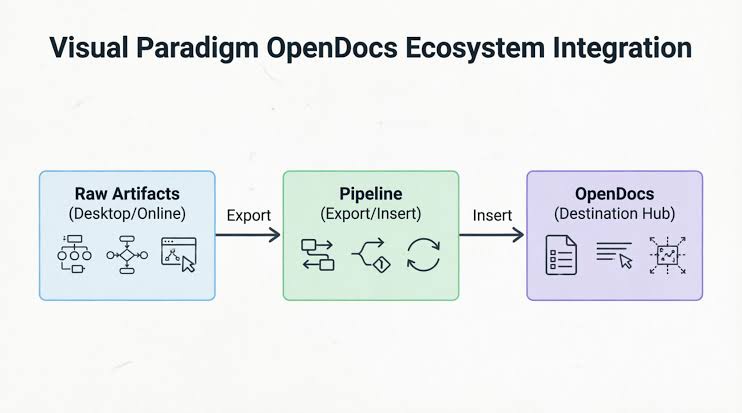
2. Tooling: The Core Components
Understanding the role of each tool is key to leveraging the full power of this ecosystem.
Visual Paradigm Desktop
The powerhouse for professional, enterprise-grade UML modeling. It provides full support for all UML 2.5 diagram types and is the primary environment for complex architectural work. Its native AI integration allows for generating fully-formed model elements directly on the canvas, maintaining traceability and professional notation standards.
OpenDocs
The destination for your technical knowledge. It is a “diagram-aware” document editor. If a source model is updated in Visual Paradigm, OpenDocs detects the discrepancy and prompts the user to sync the document, preventing version drift and ensuring stakeholders always see the current architecture.
AI Diagram Generators
Accessible within Visual Paradigm Desktop, VP Online, and the AI Chatbot. You can provide a prompt like “Generate a component diagram for a banking system” and receive a professionally structured diagram that serves as a starting point for refinement. This is a powerful way to accelerate the initial modeling phase.
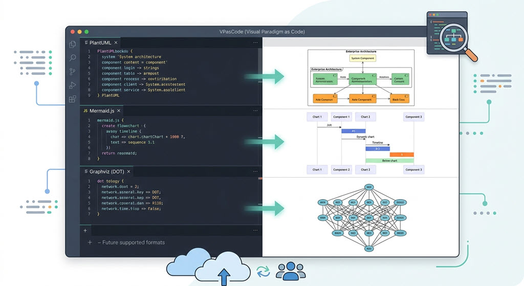
Visual Paradigm’s VPasCode
A text-to-diagram tool that supports syntaxes like PlantUML and Mermaid. It’s ideal for developers who prefer to “code their diagrams,” keeping them in sync with version control. With the Pipeline integration, a diagram created in VPasCode can be sent to OpenDocs without any manual export steps.
3. The AI-Powered Workflow
Phase 1: Ideation and Rapid Prototyping
Start by brainstorming with the AI Visual Modeling Chatbot. Describe your system concept in natural language. For example, you can ask: “Help me build a UML profile for financial trading. Include stereotypes for ‘Order’ and ‘Trade’ that extend the Class metaclass.” The AI will generate a basic diagram almost instantly, which you can then refine.
Phase 2: Refinement in Visual Paradigm Desktop
Once you have a prototype, move to Visual Paradigm Desktop for professional refinement.
-
Launch the AI Generator: Go to
Tools > AI Diagram Generation. -
Select Diagram Type: Choose your target, such as a Composite Structure Diagram, Profile Diagram, or Component Diagram.
-
Input Your Prompt: Be specific. For example: “Generate a Component Diagram for a banking application highlighting authentication service, transaction processing, account management, and notification systems.”
-
Generate and Refine: The AI will render a model on your canvas with correct UML syntax. You can then manually adjust the model, add constraints, or define tagged values. This process can reduce initial diagram creation time by up to 85% compared to traditional manual methods.
Phase 3: Documentation with OpenDocs
OpenDocs is where your model becomes a permanent part of your project’s knowledge base.
-
Inserting an AI-Generated Diagram: You can directly generate a diagram within an OpenDocs page. Click
Insert > Diagram > [Diagram Type]and then click theCreate with AIbutton to describe the diagram you need. -
Embedding from the Pipeline: For diagrams refined in Visual Paradigm Desktop, export them to the Pipeline by right-clicking the diagram and selecting
Export > Send to OpenDocs Pipeline. In OpenDocs, insert this diagram by clickingInsert > Pipelineand selecting the artifact. This creates a live link that stays current.
Phase 4: Analysis and Reporting with PlantUML
Visual Paradigm leverages PlantUML as a text-based bridge between diagrams and analysis.
-
Export to PlantUML: Your graphical UML diagrams (like Use Case, Class, or Sequence diagrams) can be exported as PlantUML code.
-
AI Report Generation: The AI Report Generator can analyze the PlantUML code of a Use Case Diagram to automatically produce a structured textual report. This report identifies actors, use cases, and relationships (
include/extend), and can even offer AI-powered insights and recommendations for improving the model.
4. Practical Examples with PlantUML Code
Here are examples of how PlantUML code is used within this ecosystem, often as the basis for AI analysis or as a portable format for version control.
Example 1: Use Case Diagram for an Online Shopping System
This diagram can be used as input for the AI Use Case Analyzer to generate reports and sub-diagrams.
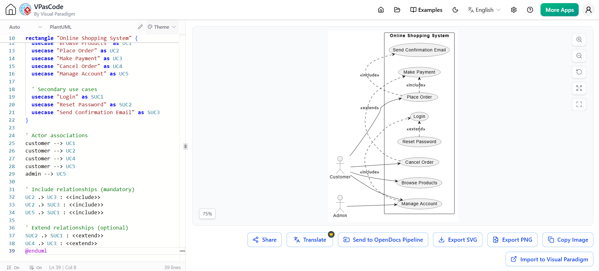
@startuml
' Use Case Diagram for Online Shopping System
left to right direction

' Define actors
actor "Customer" as customer
actor "Admin" as admin

' Define system boundary
rectangle "Online Shopping System" {
  ' Use cases
  usecase "Browse Products" as UC1
  usecase "Place Order" as UC2
  usecase "Make Payment" as UC3
  usecase "Cancel Order" as UC4
  usecase "Manage Account" as UC5

  ' Secondary use cases
  usecase "Login" as SUC1
  usecase "Reset Password" as SUC2
  usecase "Send Confirmation Email" as SUC3
}

' Actor associations
customer --> UC1
customer --> UC2
customer --> UC4
customer --> UC5
admin --> UC5

' Include relationships (mandatory)
UC2 .> UC3 : <<include>>
UC2 .> SUC3 : <<include>>
UC5 .> SUC1 : <<include>>

' Extend relationships (optional)
SUC2 .> SUC1 : <<extend>>
UC4 .> UC3 : <<extend>>
@enduml
How AI Analyzes This: The AI tool can parse this code to generate a table summarizing each use case, its actors, and its relationships (include/extend). It can also generate a focused sub-diagram centered on a specific use case like “Place Order” for more detailed analysis.
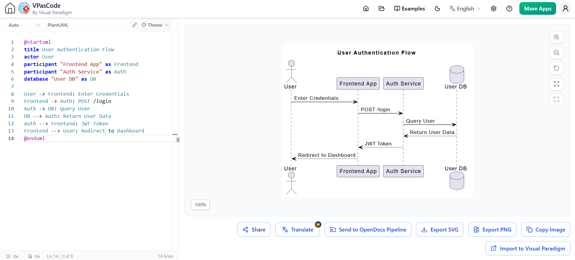
Example 2: Sequence Diagram for User Authentication
This demonstrates how developers can use VPasCode to generate diagrams directly from text.
@startuml
title User Authentication Flow
actor User
participant "Frontend App" as Frontend
participant "Auth Service" as Auth
database "User DB" as DB

User -> Frontend: Enter Credentials
Frontend -> Auth: POST /login
Auth -> DB: Query User
DB --> Auth: Return User Data
Auth --> Frontend: JWT Token
Frontend --> User: Redirect to Dashboard
@enduml
Once rendered in VPasCode, the developer can click “Send to OpenDocs Pipeline” to immediately embed this live diagram into the relevant technical specification document.
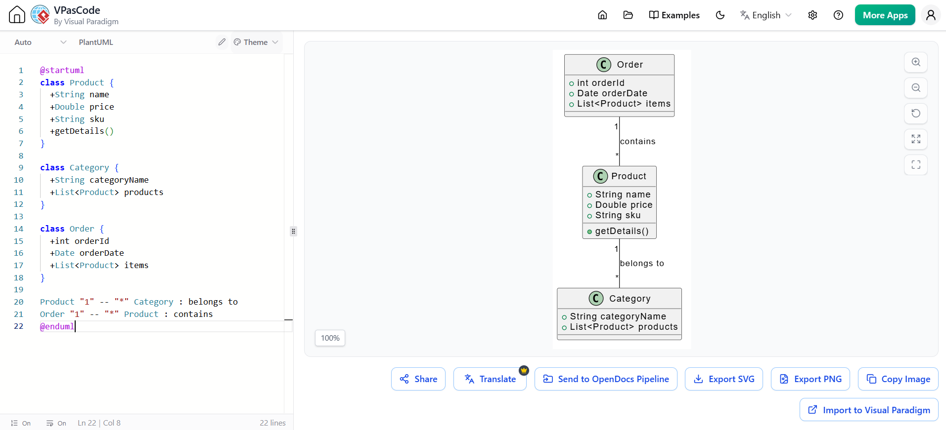
Example 3: Class Diagram for Product Management
This example showcases how a data model can be defined and maintained as code.
@startuml
class Product {
  +String name
  +Double price
  +String sku
  +getDetails()
}

class Category {
  +String categoryName
  +List<Product> products
}

class Order {
  +int orderId
  +Date orderDate
  +List<Product> items
}

Product "1" -- "*" Category : belongs to
Order "1" -- "*" Product : contains
@enduml
Benefits: This PlantUML code is portable, version-controlled, and can be seamlessly integrated into OpenDocs via the Pipeline, ensuring the class model is always part of the project’s documentation.
Transform Text into Diagrams with Visual Paradigm VPasCode
Looking for a powerful, free diagram-as-code tool? Effortlessly render PlantUML, Mermaid, Graphviz, and 20+ programming languages in real time—powered by instant AI error fixing and automatic format detection.
Conclusion
The integration of Visual Paradigm, AI, and OpenDocs represents a significant evolution in UML modeling. It moves the practice from a siloed, manual task to a collaborative, intelligent, and traceable workflow. By leveraging AI to overcome initial design hurdles and using the Pipeline to maintain a “single source of truth” between the model and its documentation, teams can create more accurate, up-to-date, and accessible technical knowledge.
This modern approach empowers software engineers to focus on solving complex design problems rather than getting bogged down in repetitive tasks, ultimately leading to faster delivery and higher-quality software systems.

![How to Model Constraints in UML? [With Examples]](https://www.archimetric.com/wp-content/uploads/2026/04/uml-constraint-example.png "How to Model Constraints in UML? [With Examples]")

 English
 Arabic
 Chinese (Simplified)
 Dutch
Dutch French
 German
 Italian
 Japanese
 Korean
 Portuguese
 Russian
 Spanish