


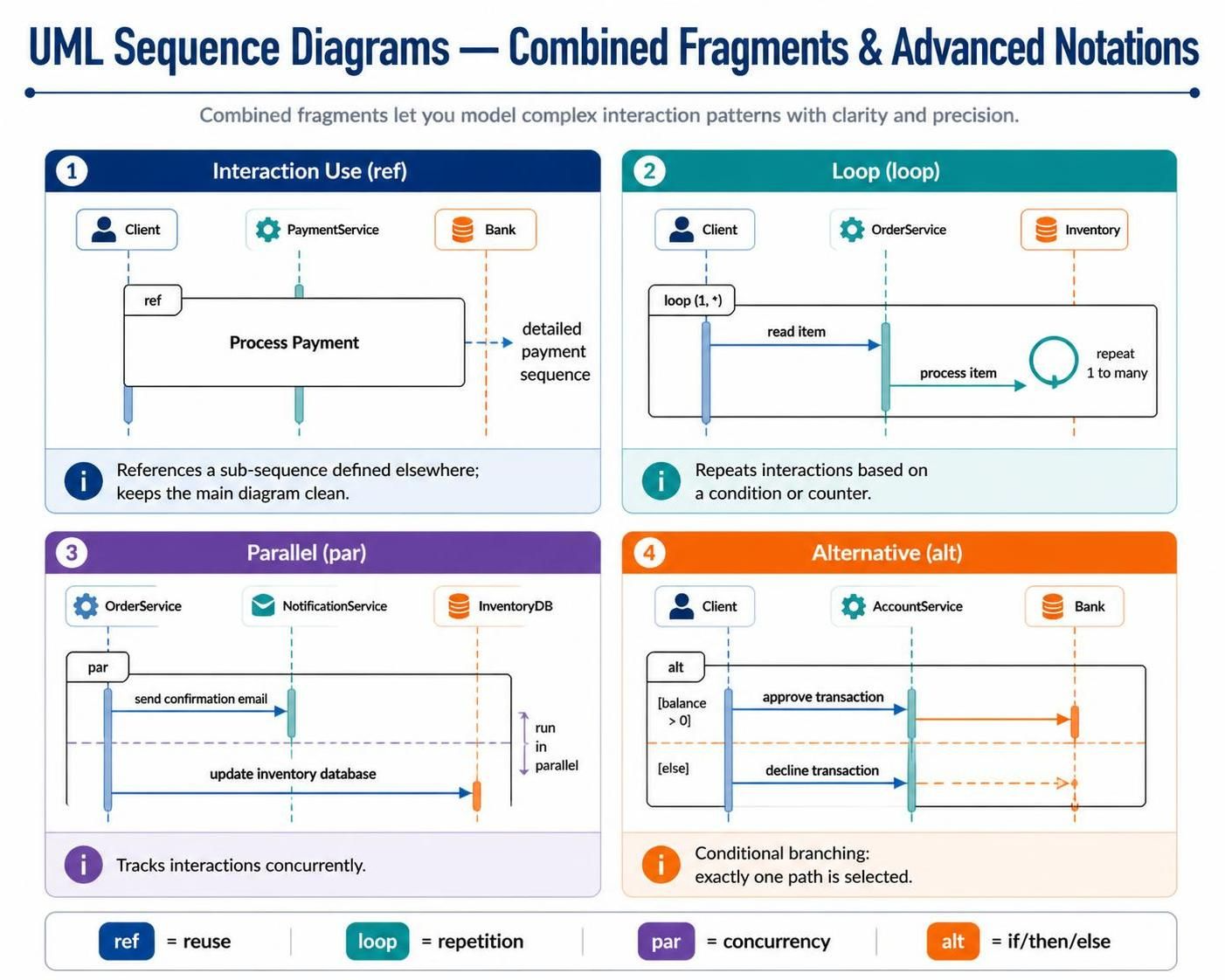
Real-world software systems are rarely linear. In the idealized world of a basic interaction, a user clicks a button and a single response comes back. However, in production environments, systems must handle complex logic, infinite loops, parallel database writes, and conditional branching. UML Sequence Diagrams provide a robust solution for modeling these complexities through Combined Fragments.
Combined fragments allow you to encapsulate specific behavioral patterns within a single diagram frame, keeping your architecture models clean and precise. In this tutorial, we will explore how to leverage Interaction Use, Loop, Parallel, and Alternative fragments to build professional-grade system models using Visual Paradigm.
1. Interaction Use (ref): Modularizing Complexity
As systems grow, sequence diagrams can become cluttered with hundreds of interaction lines. To maintain readability, UML introduces the Interaction Use fragment (often labeled as ref).
- Symbol: A box with
refin the top-left corner. - Function: It references an entire sub-sequence defined in a separate diagram.
- Best Practice: When you have a complex operation like “Process Payment” that spans 50+ steps, do not draw them all on the main overview diagram. Instead, create a “Process Payment” sub-diagram and use a
refbox to reference it.
This approach keeps your high-level architecture diagrams clean and allows you to drill down into specific details only when necessary.
2. Loop (loop): Handling Repetition
Systems frequently need to iterate over collections, retry failed operations, or poll for status updates. The Loop fragment handles these repetitive scenarios.
- Symbol: A box with
loop(min, max) in the top-left corner. - Function: Repeats the enclosed interactions based on a condition or counter.
- Example:
loop (1, )indicates the action repeats at least once, potentially infinitely. This is perfect for modeling a “Retry” mechanism or iterating through a list of unknown size.
3. Parallel (par): Modeling Concurrency
Modern distributed systems often perform multiple tasks simultaneously to optimize performance. The Parallel fragment (or par) allows you to model these concurrent tracks.
- Symbol: A box with
parin the top-left corner, divided by horizontal dashed lines. - Function: Indicates that the enclosed interaction tracks occur independently and concurrently.
- Use Case: A classic example is sending a confirmation email to a user while simultaneously updating the inventory database. These two events don’t block each other; they happen at the same time.
4. Alternative (alt): Conditional Branching
Logic often dictates that a system must choose a path based on the current state of data. The Alternative fragment models this “If/Then/Else” logic.
- Symbol: A box with
altin the top-left corner, divided into sections. - Function: Models conditional branching. Only one path is executed based on a guard condition (e.g.,
[balance > 0]). - Crucial Distinction: Unlike the
opt(option) fragment,altrequires that one of the paths must be chosen. There is no “skip” option. This is ideal for modeling strict validation logic where a transaction is either approved or declined.
Tooling: Visual Paradigm
To effectively design and manage these advanced UML notations, professional-grade tooling is essential. Visual Paradigm offers a comprehensive suite for creating, managing, and documenting complex system architectures.
With Visual Paradigm, you can:
- Drag-and-Drop Modeling: Easily add
ref,loop,par, andaltframes to your sequence diagrams with a single click. - Visual Clarity: The tool automatically manages the layout of combined fragments, ensuring that parallel tracks and loop iterations are visually distinct and easy to read.
- Code Generation: Once your model is complete, Visual Paradigm can generate the underlying boilerplate code for your chosen language, ensuring your documentation matches your implementation.

 English
 Arabic
 Chinese (Simplified)
 Dutch
Dutch French
 German
 Italian
 Japanese
 Korean
 Portuguese
 Russian
 Spanish