


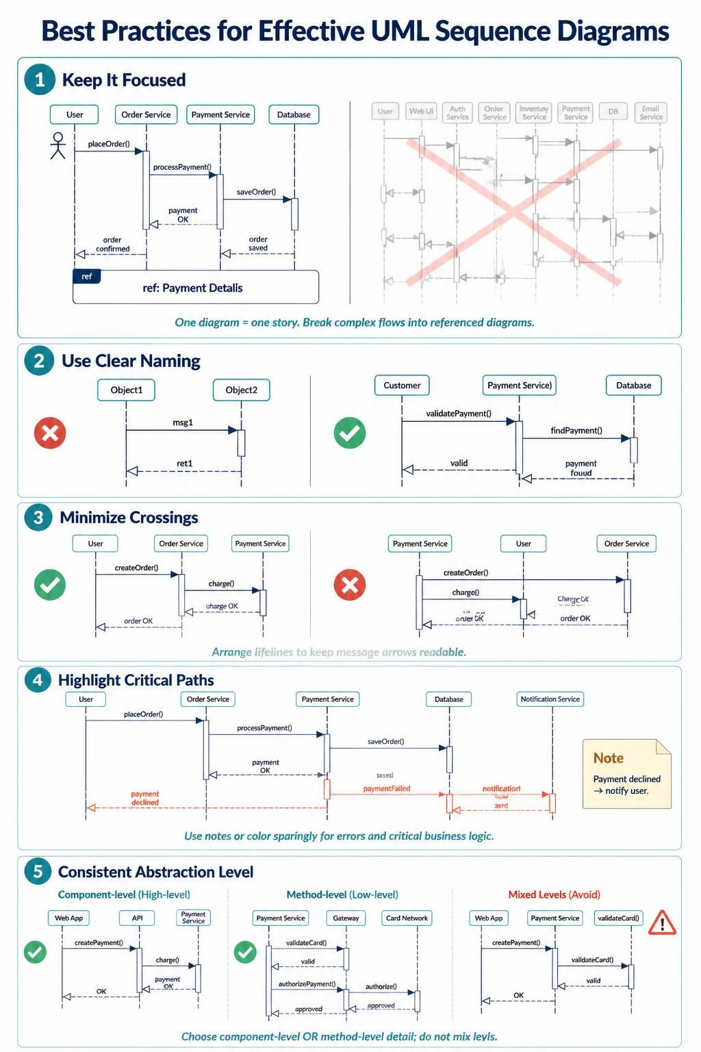
UML Sequence Diagrams are the backbone of dynamic system modeling. They provide a visual representation of the interactions between different parts of a system over time. However, creating a diagram that is both accurate and readable requires discipline. As we dive into this tutorial, we will explore the essential principles for crafting effective sequence diagrams using Visual Paradigm, ensuring your system architecture is clear to all stakeholders.
1. Keep It Focused: The One-Story Rule
A common mistake in modeling is attempting to cram an entire system’s behavior into a single, massive diagram. When a sequence diagram becomes too complex, it loses its ability to communicate effectively. The golden rule is simple: One diagram should tell one story.
If you find yourself trying to model multiple distinct use cases or a workflow that spans several pages, you should break it down. Visual Paradigm offers powerful features to handle this complexity without cluttering your view. Instead of drawing every single interaction, use ref fragments (Reference fragments) to encapsulate complex sub-processes into a single call frame. This keeps the main flow visible while allowing you to drill down into details in separate diagrams.
Visual Paradigm Tip: Managing Complexity
When modeling a complex order process, do not draw every error handling step in the main flow. Instead, identify a critical sub-process, such as “Payment Details,” and encapsulate it. This allows you to maintain a high-level overview of the “Happy Path” while referencing detailed logic elsewhere.
2. Use Clear and Descriptive Naming
Readability is paramount in technical communication. A diagram filled with generic labels like “Object1,” “msg1,” or “ret1” forces the reader to guess the intent, which defeats the purpose of visualization. Lifelines and messages should always have descriptive names.
Instead of a generic message name like msg1, use specific method calls or actions that clearly describe the operation, such as validatePayment() or checkInventory(). This approach ensures that anyone reading the diagram—whether a developer, a stakeholder, or a tester—can immediately understand the system’s behavior without needing a legend.
3. Minimize Crossings for Readability
The spatial arrangement of lifelines in a sequence diagram is not just about aesthetics; it is about cognitive load. When message arrows cross over one another excessively, the diagram becomes a “spaghetti chart” that is difficult to trace mentally. Try to arrange your lifelines so that message arrows do not cross unnecessarily.
Consider the flow of data. If a User object interacts with a Database via an Order Service, placing the lifelines in the order User – Order Service – Database creates a natural left-to-right flow. Reordering these to Database – User – Order Service will force your arrows to cross, obscuring the logical sequence of events.
The Logic of Ordering
When you encounter a diagram with too many crossings, try this simple heuristic: Group interacting objects together. If the Order Service interacts heavily with the Payment Service, place those lifelines adjacent to each other. This minimizes the distance messages need to travel visually and reduces the chance of intersections.
4. Highlight Critical Paths and Error Handling
In any robust system, the “Happy Path” is only one part of the story. Critical business logic often involves error handling, retries, or alternative flows. To make these paths stand out, use notes or colors to distinguish them from the standard flow.
For instance, a successful payment process might be represented by solid lines, while a declined payment or a timeout scenario could be represented by dashed lines with a distinct color (like red). Visual Paradigm’s styling tools allow you to easily customize the color of message arrows and notes. By highlighting these critical paths, you ensure that developers and testers immediately identify the edge cases that require the most attention.
5. Maintain Consistent Abstraction Levels
One of the most subtle yet damaging errors in modeling is mixing abstraction levels. You must decide whether you are modeling high-level component interactions (e.g., Web App talking to Payment Service) or low-level method calls (e.g., validateCard() talking to Card Network). Stick to that level within the same diagram.
Imagine a diagram that starts with a high-level component interaction but suddenly drops down to specific SQL queries or internal function calls. This confuses the reader because the context shifts unexpectedly. Always choose one level of detail and maintain it throughout the entire diagram. If you need to show both high-level and low-level details, split them into two separate diagrams.
Summary
Effective UML modeling is an exercise in clarity and communication. By keeping your diagrams focused, using descriptive names, minimizing crossings, highlighting critical paths, and maintaining consistent abstraction levels, you create diagrams that truly serve the system architecture. Visual Paradigm provides the toolset to execute these best practices, turning complex system logic into clear, actionable blueprints.

 English
 Arabic
 Chinese (Simplified)
 Dutch
Dutch French
 German
 Italian
 Japanese
 Korean
 Portuguese
 Russian
 Spanish