


Designing a robust software system begins not with writing code, but with understanding the story of how that system will be used. In the realm of Object-Oriented Design, the Use Case Diagram serves as the primary blueprint for this narrative. It acts as a vital communication bridge, translating abstract user needs into concrete functional requirements that developers can implement.
This tutorial explores the architecture of a classic Library Management System. We will dissect the roles of the system’s inhabitants, the boundaries of its operations, and the specific interactions that define its value.
Deconstructing the System Boundary
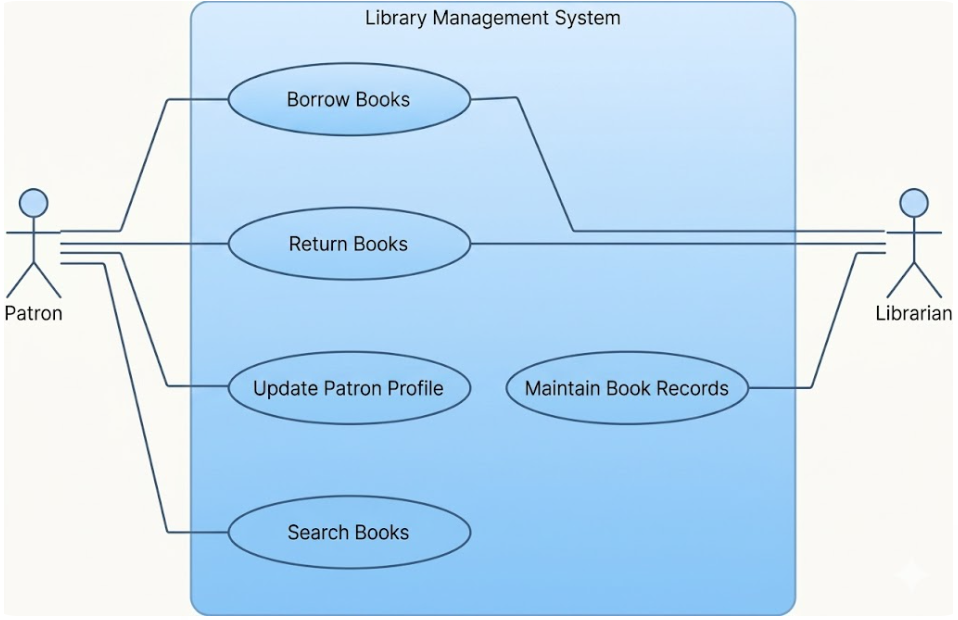
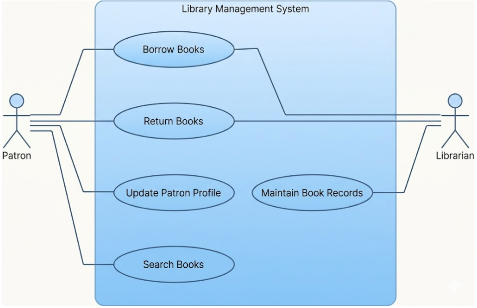
At the heart of every use case diagram is the System Boundary. In our example, this is represented by the large, light-blue rectangle labeled Library Management System.
This boundary serves a critical architectural purpose: it defines the scope of the project. Everything inside the rectangle is part of the software’s responsibility. Everything outside—such as the human users or external hardware—is considered part of the environment.
- Internal Elements: The ovals (ellipses) inside the box represent the actual functionality, or “Use Cases,” that the software must execute.
- External Elements: The stick figures outside the box represent the “Actors” who initiate these actions.
Identifying the Actors
Actors are the users of the system, but they represent roles rather than specific individuals. In this model, we have two distinct actors:
- Patron: Represented by the stick figure on the left. This role encompasses library members who wish to access services. Note that the Patron is the primary initiator of most activities in the diagram.
- Librarian: Represented by the stick figure on the right. This role belongs to the staff member responsible for managing the inventory. Their interaction is more specialized, focusing on backend administration.
It is important to remember that actors always reside outside the system boundary. The system cannot “be” the patron; it can only respond to the patron’s requests.
Analyzing the Use Cases
The ovals inside the system boundary are the Use Cases. Each oval represents a specific unit of functionality that provides a tangible benefit to an actor. Let’s break down the five use cases presented in this diagram:
- Borrow Books: The process of checking out an item. This is a core transaction for the system.
- Return Books: The process of checking an item back in. This triggers updates to the availability of the book.
- Update Patron Profile: A management function allowing the patron to maintain their own data (e.g., changing an address or password).
- Search Books: The query function allowing users to find items in the catalog.
- Maintain Book Records: The administrative function for adding new books, deleting records, or updating metadata.
Mapping Relationships and Associations
The lines connecting actors to use cases are called Associations. They indicate a relationship where the actor participates in the use case.
Notice the distinct interaction patterns in this diagram:
The Patron’s Scope
The Patron has a broad range of access, indicated by the multiple lines connecting to Borrow Books, Return Books, Update Patron Profile, and Search Books. This shows the system is designed to be user-friendly for self-service.
The Librarian’s Scope
The Librarian has a more focused scope. The association line connects directly to Maintain Book Records. Interestingly, there is also a line connecting the Librarian to the Return Books use case. This implies that while Patrons can return books (perhaps via a kiosk or app), the system also allows a human staff member to handle returns, perhaps for damaged items or special collections.
Visualizing the Model with VPasCode
To replicate this diagram using the Visual Paradigm UML tool, you would typically construct the model by defining the system container first, then dragging and dropping the Actor and Use Case elements. Below is a representation of how the structure is logically defined, similar to the syntax used in model generation tools.
System "Library Management System" {

  # Define Actors
  Actor "Patron" as Patron
  Actor "Librarian" as Librarian

  # Define Use Cases
  UseCase "Borrow Books" as Borrow
  UseCase "Return Books" as Return
  UseCase "Update Patron Profile" as Profile
  UseCase "Search Books" as Search
  UseCase "Maintain Book Records" as Records

  # Define Associations
  Patron --> Borrow
  Patron --> Return
  Patron --> Profile
  Patron --> Search

  Librarian --> Return
  Librarian --> Records
}
Conclusion
This Library Management System diagram is a perfect example of how to abstract complex requirements into a clear, visual format. By identifying who the actors are and what they need to do, developers can prioritize features. For instance, the “Search Books” and “Borrow Books” functions are likely critical path items, while “Maintain Book Records” is a backend utility. This clarity ensures that the final software product aligns perfectly with the needs of the library’s patrons and staff.

 English
 Arabic
 Chinese (Simplified)
 Dutch
 French
 German
 Italian
 Japanese
 Korean
 Portuguese
 Russian
 Spanish