


Your progression makes sense, with one important distinction: UML Activity Diagrams are not simply “extended flowcharts,” and BPMN is not just a more powerful-looking flowchart. They are different notations for different modeling needs.
A practical path is:
Flowchart → UML Activity Diagram → BPMN collaboration/process model → validated, executable BPMN model (when execution is actually needed).
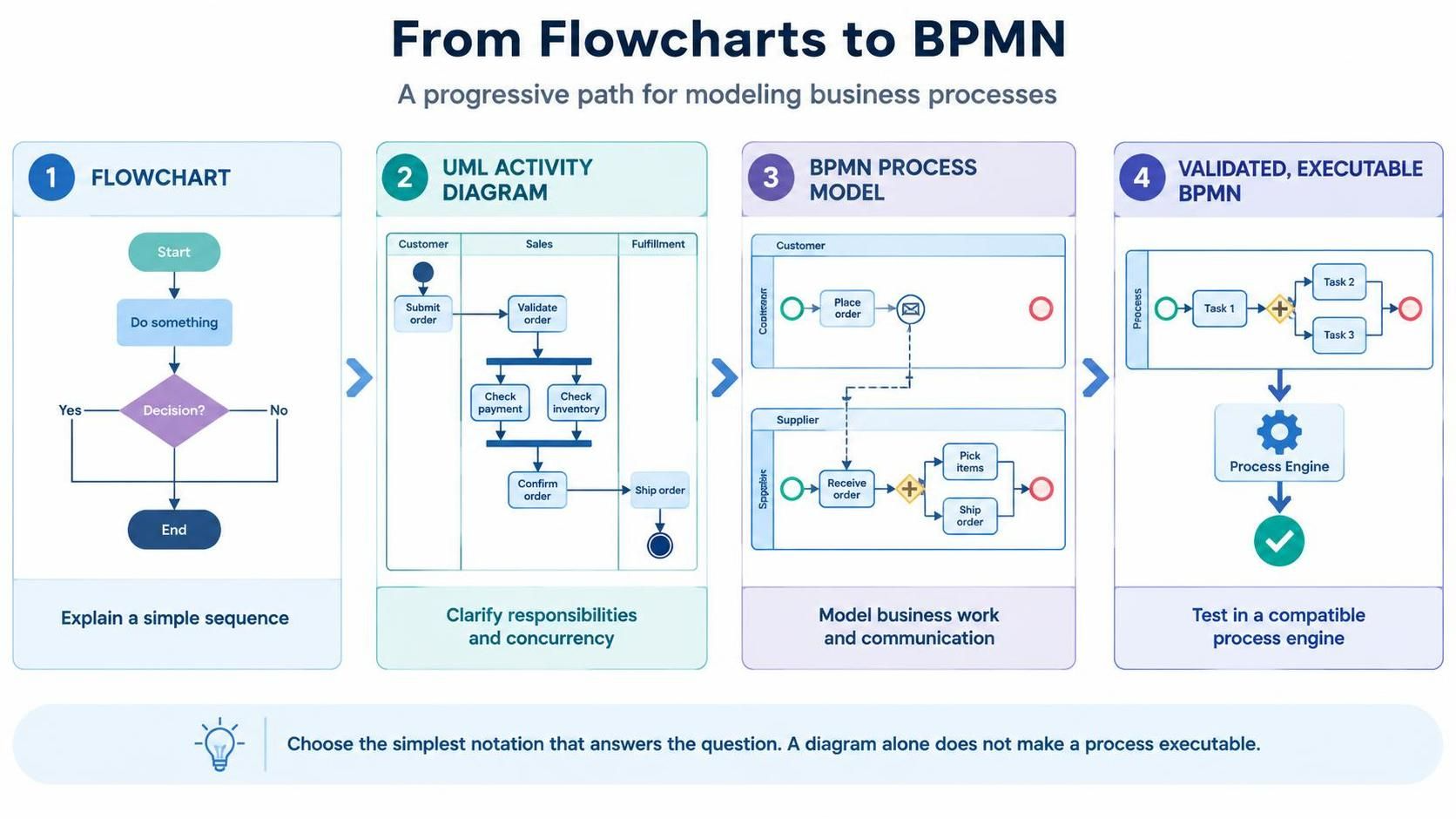
Each step adds precision. You do not need to replace an earlier diagram every time: a simple flowchart may remain the clearest way to explain a straightforward process.
1. What each notation is for
| Notation | Best for | What it adds | Typical audience |
|---|---|---|---|
| Flowchart | Explaining a short, simple sequence | Familiar actions, decisions, and outcomes | Almost anyone |
| UML Activity Diagram | Modeling detailed workflows or system behavior | Partitions, explicit concurrency and synchronization, and richer control flow | Analysts, designers, developers |
| BPMN | Modeling business processes across roles, organizations, or systems | Standardized events, gateways, pools, message flows, timers, exceptions, and process semantics | Business, operations, and implementation teams |
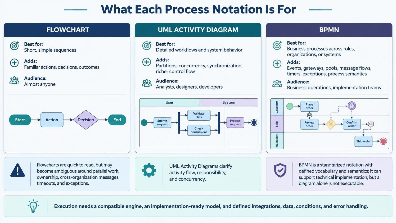
A flowchart is quick to read, but can become ambiguous when it tries to show parallel work, who owns each task, messages between organizations, timeouts, or exception handling. A UML Activity Diagram can make activity flow, responsibilities, and concurrent behavior clearer; Visual Paradigm describes it as an advanced form of flowcharting and supports partitions for grouping activities.
BPMN is an OMG standard intended to be understandable to business stakeholders while still being precise enough to support technical implementation. Its added power comes from its defined vocabulary and semantics—not simply from having more symbols.
BPMN does not automatically make a process executable. A diagram can be used for communication or analysis without being ready for a process engine. Execution requires a compatible engine, an implementation-ready model, and concrete details such as service integrations, data, conditions, and error behavior. Visual Paradigm Desktop supports BPMN modeling, but verify that the edition you have includes the feature you need.
2. Learn by modeling one process repeatedly
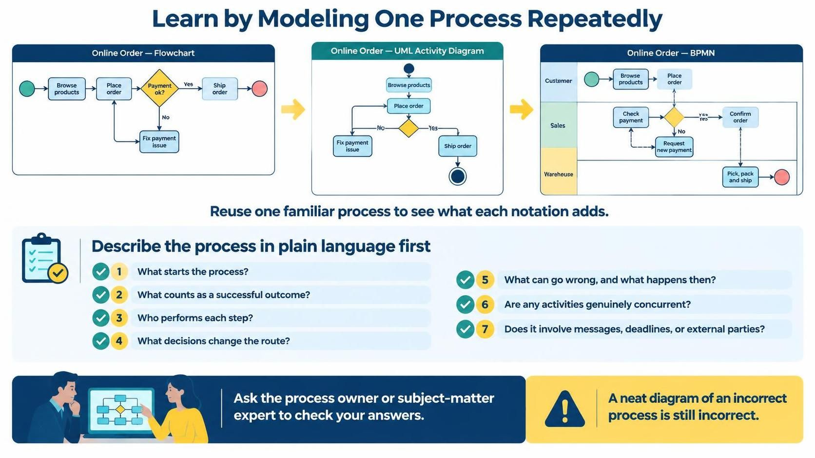
Pick a process you understand well, such as handling an online order. Keep using that example as you learn. It is easier to see what each notation contributes when you are refining the same process instead of learning a new business domain at every stage.
For each model, first write a short plain-language description:
-
What starts the process?
-
What counts as a successful outcome?
-
Who performs each step?
-
What decisions change the route?
-
What can go wrong, and what happens then?
-
Are any activities genuinely concurrent?
-
Does the process involve messages, deadlines, or external parties?
Have a process owner or subject-matter expert check the answers. A neat diagram of an incorrect process is still incorrect.
3. Stage one: make clear flowcharts
Start with only a few symbols: start/end, activity, decision, and arrows. Give activities short, verb-led names—“Check stock,” not “Stock”—and write decisions as questions, with each outgoing branch labeled, such as “Available?” → “Yes” or “No.”
Keep the first diagram focused on the normal path and one or two important alternatives. Avoid trying to show every technical detail or policy exception at once. Your goal is a shared, understandable account of the process.
Example 1: basic flowchart-style activity
Paste this into VPasCode as PlantUML:
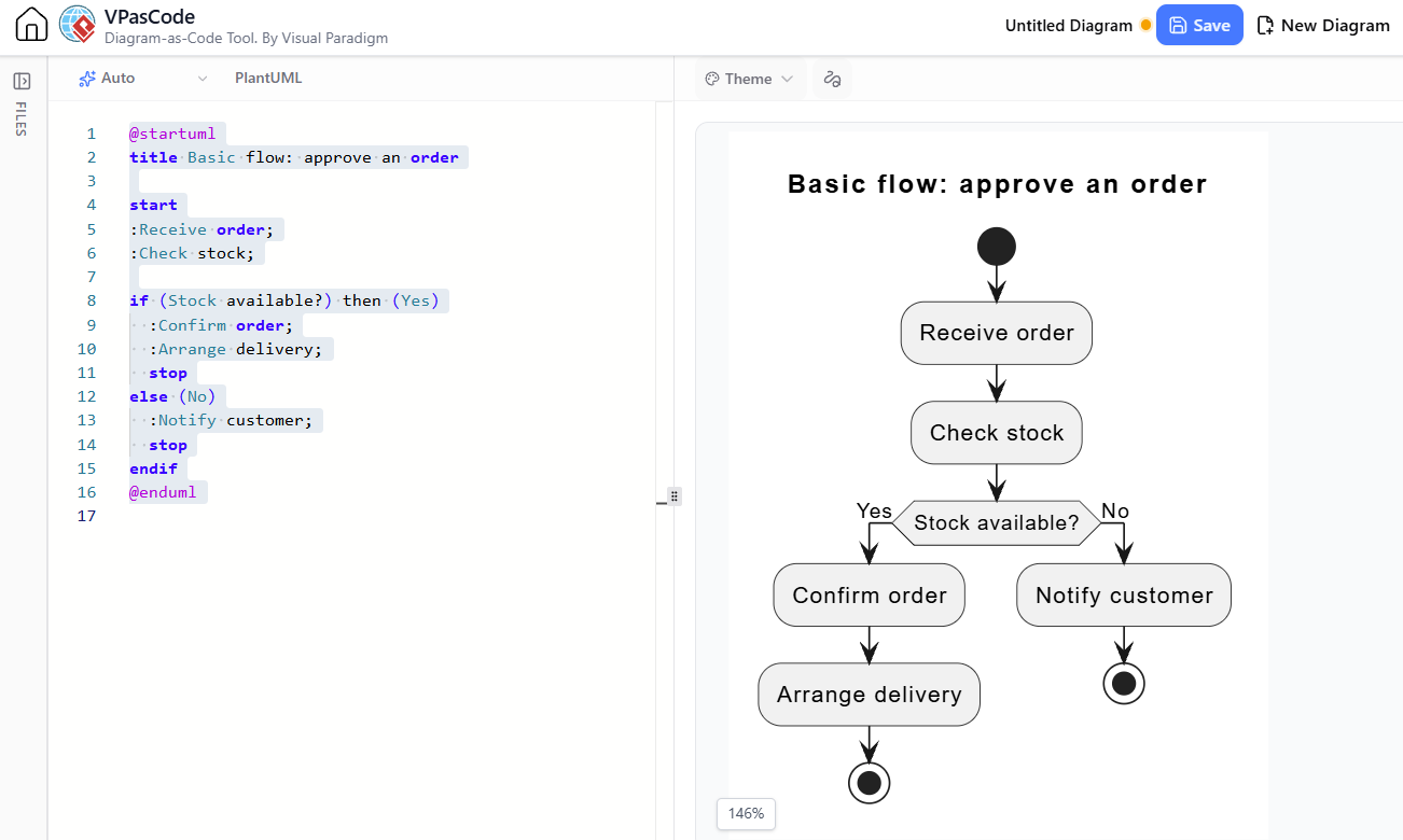
@startuml
title Basic flow: approve an order

start
:Receive order;
:Check stock;

if (Stock available?) then (Yes)
  :Confirm order;
  :Arrange delivery;
  stop
else (No)
  :Notify customer;
  stop
endif
@enduml
This is intentionally simple. It shows a decision and its outcomes, but says little about which roles perform the work or how an external response is handled.
Move on when: another person can follow the diagram without you narrating it, and the decision branches have clear outcomes.
4. Stage two: add UML Activity Diagram concepts
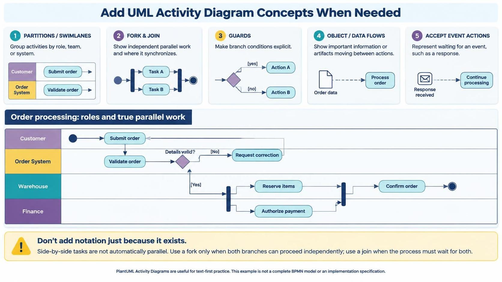
Once a flowchart is becoming crowded or unclear, learn the Activity Diagram concepts that solve a specific problem:
-
Partitions (swimlanes): group activities by role, team, or system.
-
Fork and join: show work that happens in parallel and where it synchronizes.
-
Guards: make the condition on a branch explicit.
-
Object or data flows: show important information or artifacts moving between actions.
-
Accept event actions: represent waiting for an event, such as a response.
Do not add these just because the notation allows them. For example, two tasks shown side by side are not necessarily parallel. Use a fork only when both branches can proceed independently, and a join only when the process must wait for both.
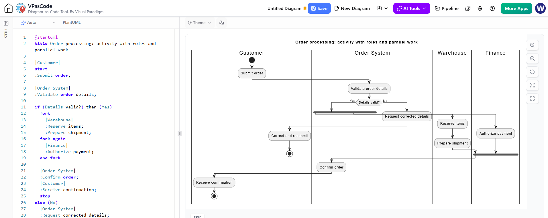
PlantUML’s activity syntax is useful for text-first practice and rendering. The following example uses lanes and parallel branches. Its purpose is to express the workflow; it is not a complete BPMN model or an implementation specification.
Example 2: responsibility and parallel work
@startuml
title Order processing: activity with roles and parallel work

|Customer|
start
:Submit order;

|Order System|
:Validate order details;

if (Details valid?) then (Yes)
  fork
    |Warehouse|
    :Reserve items;
    :Prepare shipment;
  fork again
    |Finance|
    :Authorize payment;
  end fork

  |Order System|
  :Confirm order;
  |Customer|
  :Receive confirmation;
  stop
else (No)
  |Order System|
  :Request corrected details;
  |Customer|
  :Correct and resubmit;
  stop
endif
@enduml
This makes role ownership and parallel work easier to discuss. However, a business stakeholder might still ask: What if the payment is declined? What if stock cannot be reserved? Is the customer waiting for a message or does the system proceed asynchronously? Those questions are signs that you may need a more process-oriented model.
Move on when: you need clearer ownership, coordination, or system behavior than a simple flowchart can express—and you can explain why each added UML element is necessary.
5. Stage three: learn BPMN in layers
BPMN has a broad set of elements. Begin with a deliberately small subset, then expand it only as real process requirements call for it.
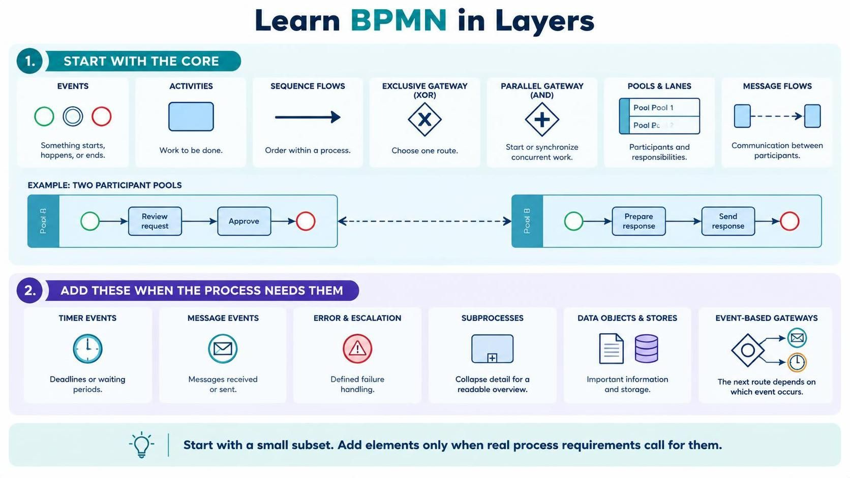
First learn the core elements
-
Events: circles that represent something starting, happening, or ending.
-
Activities: work, commonly shown as rounded rectangles.
-
Sequence flows: solid arrows that show order within a process.
-
Exclusive gateway (XOR): route down one chosen path, such as approved versus rejected.
-
Parallel gateway (AND): start concurrent branches or synchronize them.
-
Pools and lanes: show participants and responsibility boundaries.
-
Message flows: show communication between separate participants, rather than order of steps within one participant.
Then add other concepts as needed:
-
Timer events for deadlines or waiting periods.
-
Message events for received or sent communications.
-
Error and escalation handling for failures that need defined outcomes.
-
Subprocesses to collapse detail and keep an overview readable.
-
Data objects and stores to identify important information.
-
Event-based gateways when the next route depends on which event occurs.
A useful rule is: sequence flow shows control within a process; message flow shows communication between participants. Do not use message flow as a substitute for sequence flow inside a single participant.
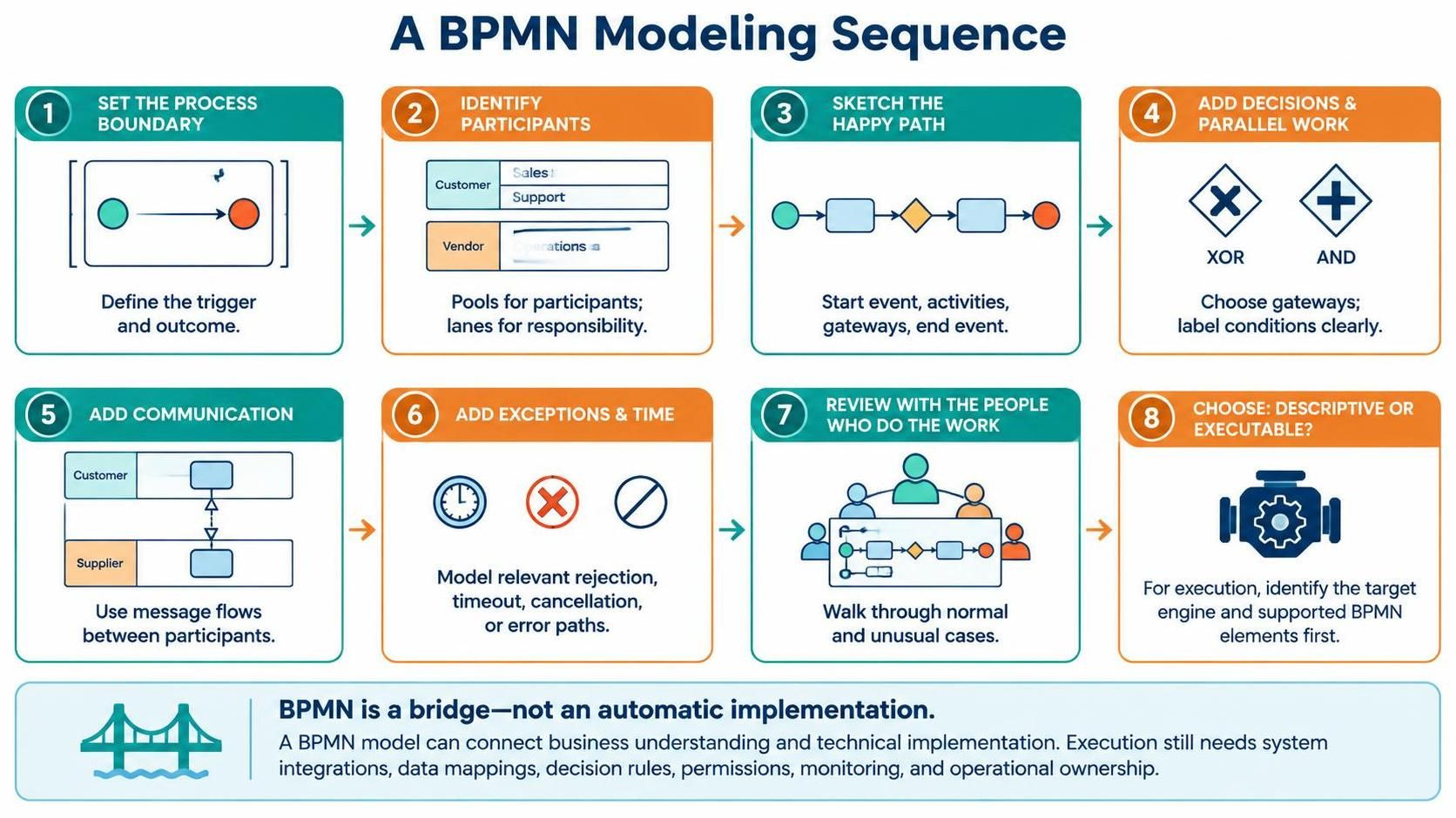
A BPMN modeling sequence
-
Set the process boundary. State what triggers the process and what outcome it covers.
-
Identify participants. Decide which people, teams, organizations, or systems are separate participants. Use pools for participants and lanes to organize responsibility within a participant.
-
Sketch the happy path. Use start event, activities, gateways, and end event.
-
Add decisions and parallel work. Choose the appropriate gateway and make conditions understandable.
-
Add communication. Use message flows between participants where a message or interaction matters.
-
Add exceptions and time behavior. Include only relevant rejection, timeout, cancellation, or error paths.
-
Check the model with the people who do the work. Walk through real cases, including unusual ones.
-
Decide whether it is descriptive or executable. If execution is a goal, identify the target process engine and its supported BPMN elements before designing implementation details.
An important benefit of BPMN is that it provides a shared notation that can bridge business process design and technical implementation. But that bridge still needs a real implementation: system calls, data mappings, decision rules, permissions, monitoring, and operational ownership do not appear automatically just because the diagram is BPMN.
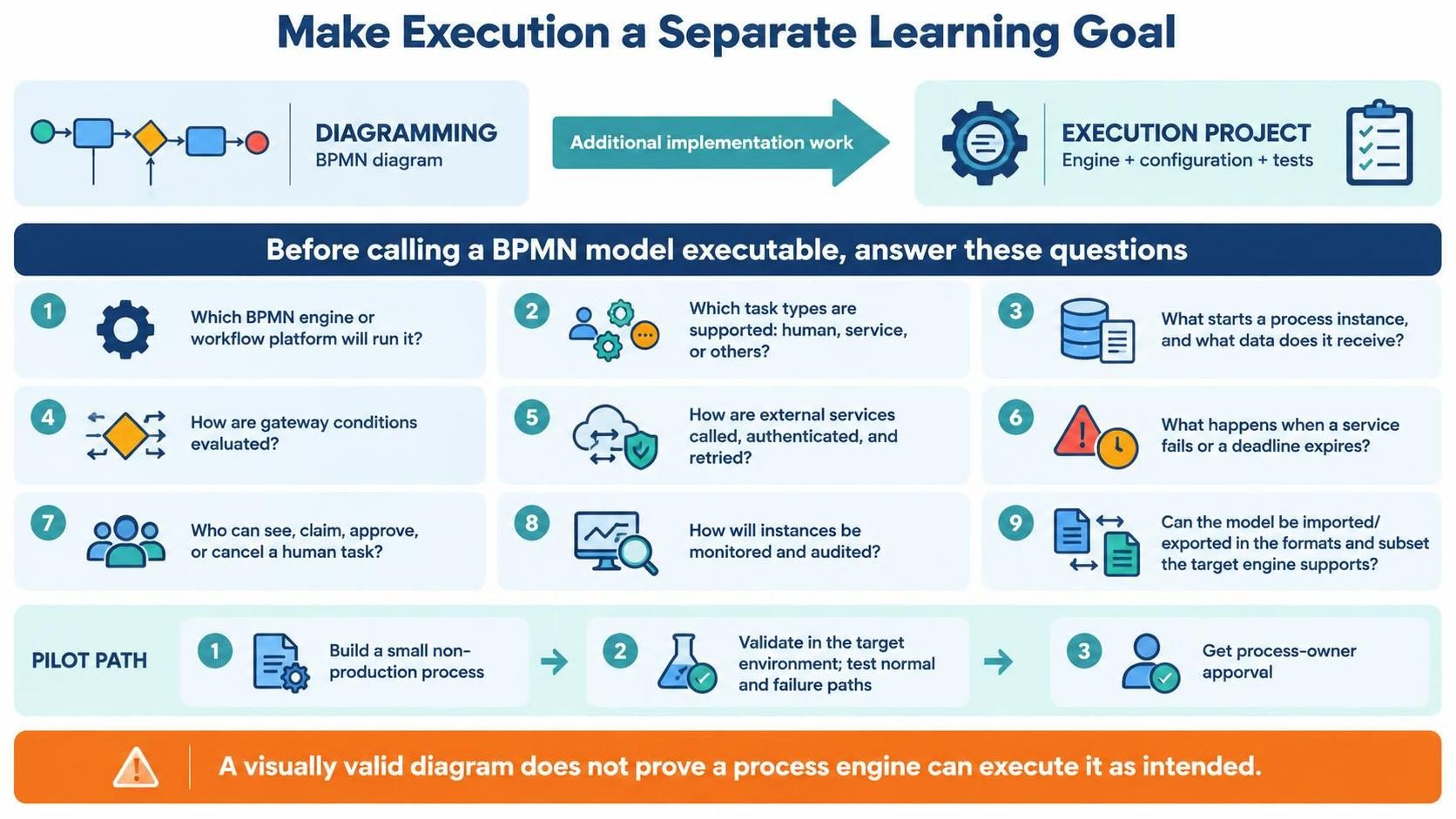
6. Stage four: make execution a separate learning goal
Treat execution as its own project, not as the final checkbox in a diagramming exercise.
Before calling a BPMN model executable, work through questions such as:
-
Which BPMN engine or workflow platform will run it?
-
Which tasks are human tasks, service tasks, or other supported task types?
-
What starts an instance, and what data does it receive?
-
How are gateway conditions evaluated?
-
How are external services called, authenticated, and retried?
-
What happens when a service fails or a deadline expires?
-
Who can see, claim, approve, or cancel a human task?
-
How will process instances be monitored and audited?
-
Can the model be exported and imported in the formats and subset the target engine supports?
Test execution with a small, non-production process first. Validate the model in the target environment, test normal and failure paths, and have process owners approve the expected behavior. A visually valid diagram is not proof that a process engine can execute it as intended.
7. A beginner-friendly practice plan
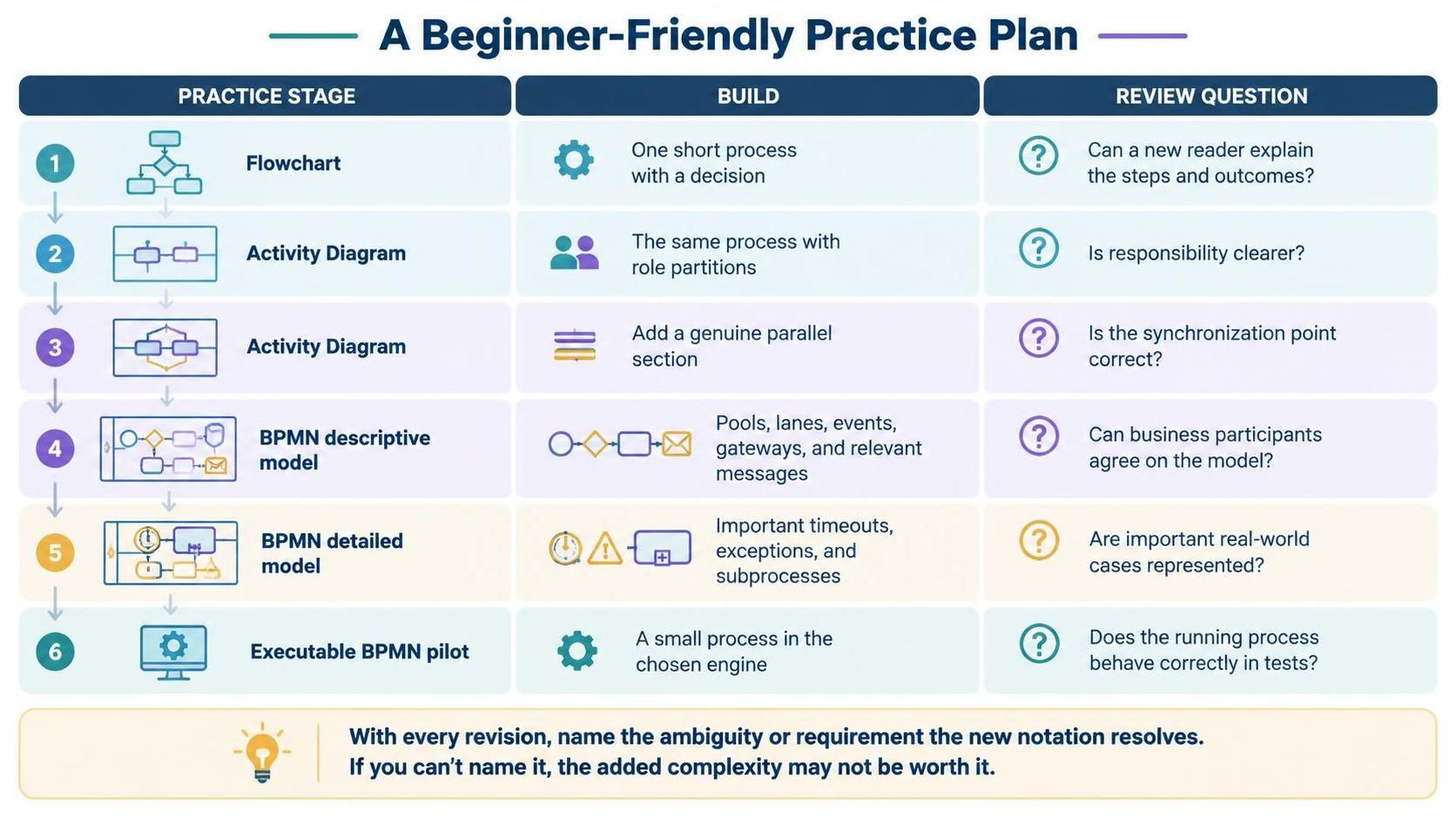
Use a small deliverable at each stage rather than trying to learn all three notations at once.
| Practice stage | Build | Review question |
|---|---|---|
| Flowchart | One short process with a decision | Can a new reader explain the steps and outcomes? |
| Activity Diagram | The same process with role partitions | Is responsibility clearer? |
| Activity Diagram | Add a genuine parallel section | Is the synchronization point correct? |
| BPMN descriptive model | Pools, lanes, events, gateways, and relevant messages | Can business participants agree on the model? |
| BPMN detailed model | Important timeouts, exceptions, and subprocesses | Are important real-world cases represented? |
| Executable BPMN pilot | A small process in the chosen engine | Does the running process behave correctly in tests? |
For each revision, compare the new diagram with the previous one and explain what ambiguity or requirement the new notation resolves. If you cannot name the problem it solves, the added complexity may not be worth it.
8. How to use Visual Paradigm Desktop, AI Chatbot, VPasCode, and OpenDocs together
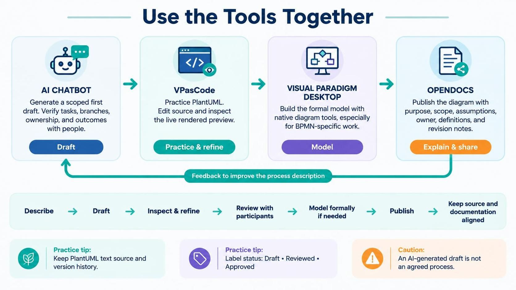
Use each tool for a different part of the work:
-
AI Chatbot — generate a starting point. Give it a scoped process description and ask for a specific notation. Treat its result as a draft: verify tasks, branch conditions, ownership, and missing outcomes with a human. Visual Paradigm documents AI-based diagram generation, and its product information describes support for flowcharts, Activity Diagrams, and BPMN; available features may depend on edition.
-
VPasCode — practice and refine diagram code. Paste PlantUML into its editor, use the rendered preview to inspect the result, and revise the source as you learn. VPasCode supports PlantUML and live rendering. It is a good match for the PlantUML Activity Diagram examples here.
-
Visual Paradigm Desktop — develop the formal model. Use its native diagram editor when the work needs structured modeling, team/project integration, or BPMN-specific elements. Desktop’s feature matrix lists both Activity Diagrams and BPMN, though availability varies by edition.
-
OpenDocs — explain and publish the model. Put the diagram beside its purpose, scope, assumptions, owner, definitions, and revision notes. VPasCode documents an OpenDocs publishing workflow for finished diagrams.
A sensible loop is:
Describe → generate a draft → inspect and refine → review with process participants → model formally in Desktop if needed → publish with its explanation → update the source and documentation together.
Keep a text source for PlantUML diagrams, use clear filenames and version history, and label the published diagram with its status—for example, draft, reviewed, or approved. Avoid presenting a draft produced by AI as an agreed process.
9. Where PlantUML fits—and where it doesn’t
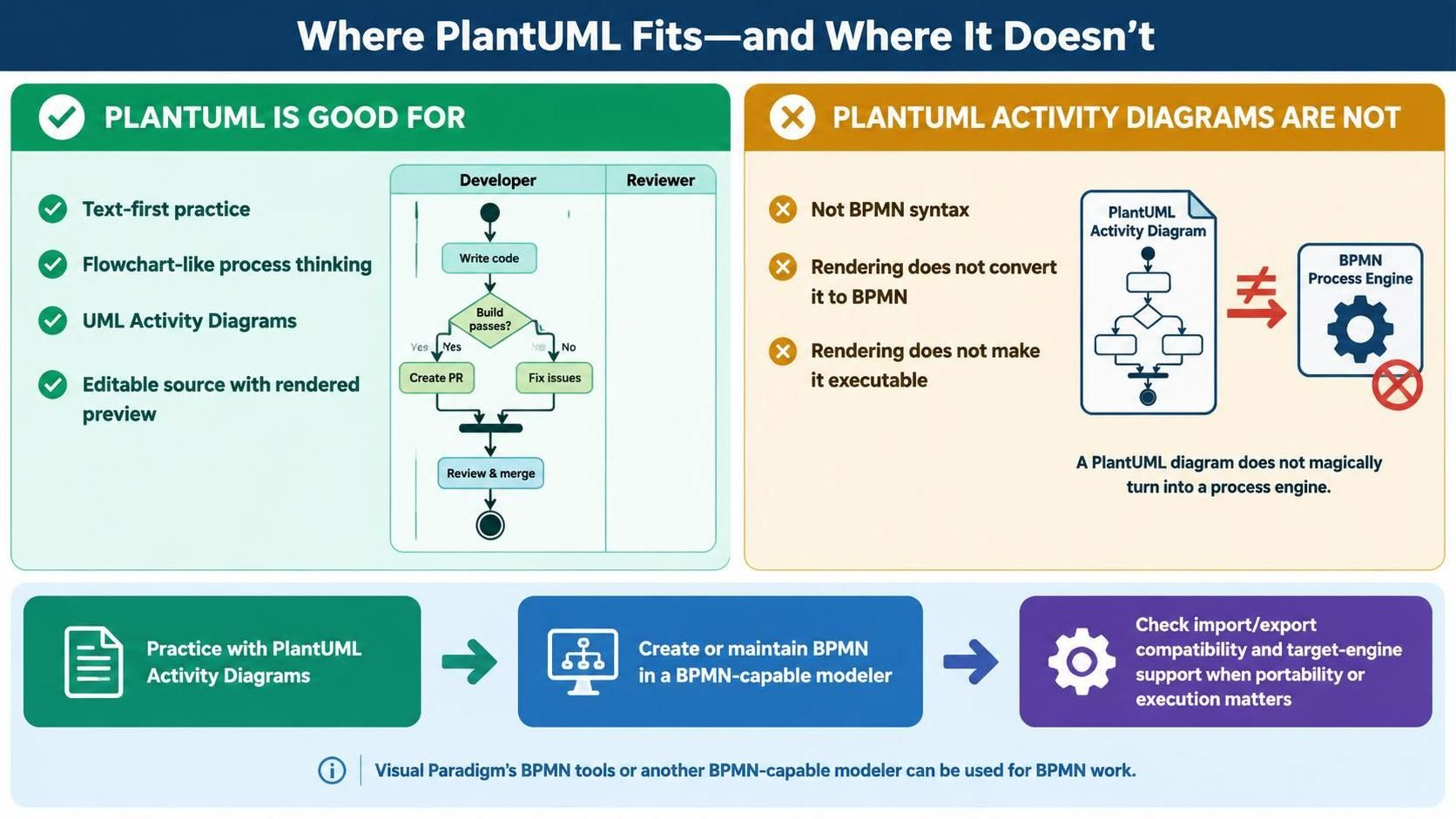
PlantUML is useful here for practicing flowchart-like and UML Activity Diagram thinking as text. The examples above are PlantUML Activity Diagrams. They are not BPMN syntax, and rendering an Activity Diagram does not convert it into BPMN or make it executable.
When you reach BPMN, create or maintain the BPMN model using Visual Paradigm’s BPMN support or another BPMN-capable modeler. Confirm the target tool’s BPMN import/export and execution support if portability or runtime use matters.
10. A quick checklist for reviewing any process diagram
Before sharing a diagram, check:
-
Scope: Are the start and end boundaries clear?
-
Actions: Are steps named with clear verbs?
-
Decisions: Are branch conditions explicit, and are the outcomes covered?
-
Responsibility: Is it clear who performs each action?
-
Sequence: Do arrows represent the intended order?
-
Concurrency: Is work genuinely parallel, and does the process synchronize correctly?
-
Communication: Are interactions between participants distinguished from internal sequence?
-
Exceptions: Are the important failure, rejection, and timeout cases addressed?
-
Audience: Is the notation appropriate for the readers?
-
Execution claim: Is this a descriptive diagram, or has the model actually been prepared and tested for a specific engine?
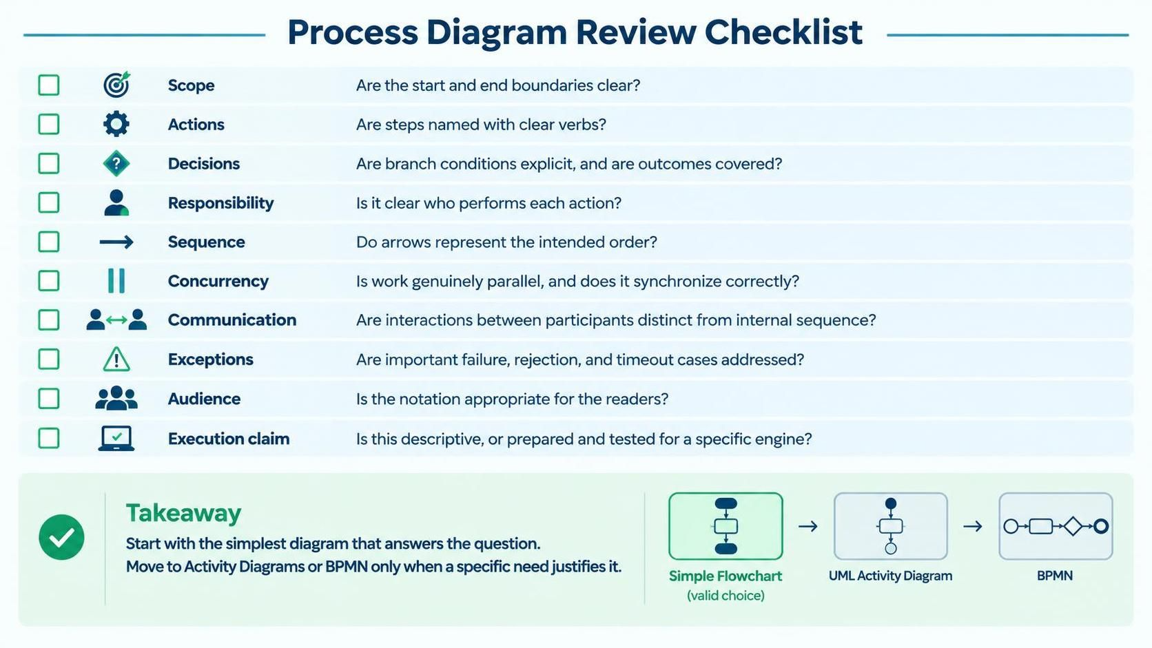
The best beginner strategy is to make the simplest diagram that answers the current question, then move to Activity Diagrams or BPMN when a specific modeling need justifies it. That builds skill progressively without teaching people that every workflow requires the most elaborate notation.

 English
 Arabic
 Chinese (Simplified)
 Dutch
 French
 German
 Italian
 Japanese
 Korean
 Portuguese
 Russian
 Spanish