


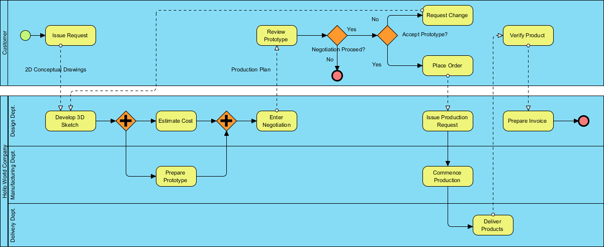
In the realm of enterprise process management, clarity is currency. When organizations attempt to automate complex workflows without a standardized language, they often face misalignment between what the business wants and what the software delivers. This tutorial explores Business Process Model and Notation (BPMN), the global standard for visualizing these workflows. We will dissect a comprehensive process diagram to understand how BPMN bridges the gap between strategic goals and technical execution.
Understanding the BPMN Landscape
BPMN is not merely a drawing tool; it is a rigorous notation system designed to be read by two distinct audiences: Business Users (who define the rules) and Technical Experts (who automate the logic). Its evolution from the Business Process Management Initiative (BPMI) to the Object Management Group (OMG) has solidified it as an international standard (ISO/IEC 19510).
By adopting BPMN, organizations achieve:
- Standardization: A universal syntax that eliminates ambiguity.
- Clarity: A visual representation that is easy to understand, regardless of technical background.
- Scalability: The ability to model simple transactions or intricate enterprise architectures.
Decoding the Swimlane Architecture
One of the most powerful features of BPMN is the Swimlane (or Pool/Swimlane) architecture. This visual structure organizes processes by responsibility, ensuring that every activity is clearly assigned to a specific role, department, or system.
Let us analyze the swimlanes presented in our reference diagram:
- Customer (Top Lane): Represents external entities or users initiating requests. This lane focuses on high-level business decisions, such as reviewing prototypes and accepting production plans.
- Design Dept. (Middle Lane): Represents the creative and planning phase. This includes tasks like developing 3D sketches, estimating costs, and entering negotiations.
- Manufacturing Dept. (Bottom Lane): Focuses on the physical realization of the product. Activities here include preparing prototypes and commencing production.
- Delivery Dept. (Bottom Lane): Handles the final handover and logistics, concluding with the delivery of products.
Technical Analysis: The Request-to-Delivery Workflow
Now, let us walk through the logic flow of the diagram, focusing on the technical elements that drive the process forward.
1. The Process Trigger
The workflow begins with a Start Event (the green circle) in the Customer lane. The action Issue Request is triggered by the creation of 2D Conceptual Drawings. This is an example of a Message Flow (dashed line) passing data to the Design Department.
2. Parallel Processing and Forks
Notice the black square with a plus sign in the Design Dept. lane. This is a Parallel Gateway (XOR vs. AND).
- The process reaches a fork where the flow splits simultaneously.
- One branch moves forward to Estimate Cost.
- The other branch splits further to Prepare Prototype.
This demonstrates BPMN’s ability to model concurrent activities, significantly reducing the total cycle time of the project.
3. Decision Logic (Gateways)
As the process moves to the right, we encounter diamond shapes known as Gateways. These control the branching logic:
- Negotiation Proceed?: An exclusive gateway (white diamond). If the cost is too high or terms are not met (No), the process terminates or loops back.
- Accept Prototype?: A critical decision point. If the Customer accepts (Yes), the flow moves to Place Order. If rejected (No), it loops back to Request Change.
4. Inter-Swimlane Communication
One of the most complex aspects of BPMN is managing interactions between lanes. The diagram utilizes Message Flows (dashed lines with an open circle at the start and a filled triangle at the end) to represent hand-offs.
For instance, when the Design Department completes the Enter Negotiation task, they send a “Production Plan” message back to the Customer lane. This visualizes the asynchronous nature of business communication.
Tooling for Success: Visual Paradigm
To effectively model these complex diagrams, technical teams require robust software. Visual Paradigm is a leading platform that supports the full BPMN 2.0 specification. It allows users to design diagrams that are not only visually accurate but also executable. With its built-in BPMN modeling capabilities, teams can ensure that the logic defined in the swimlanes translates accurately into executable code or process definitions.
Conclusion
This diagram illustrates a robust “Order-to-Delivery” lifecycle. By utilizing BPMN’s swimlanes, gateways, and message flows, the organization has created a transparent roadmap that aligns the Customer, Design, Manufacturing, and Delivery departments. This alignment is the key to efficient process execution and continuous improvement.

 English
 Arabic
 Chinese (Simplified)
 Dutch
Dutch French
 German
 Italian
 Japanese
 Korean
 Portuguese
 Russian
 Spanish