


In the complex world of Business Process Model and Notation (BPMN), visual clarity is paramount. When designing system architectures or modeling business interactions, one of the most critical distinctions a modeler must make is between what happens inside a process and what happens between processes.
This tutorial explores the specific diagrammatic element shown in the image above: the Message Flow. We will dissect how dotted lines with arrows represent the exchange of information between different entities (pools) and contrast this with internal sequence flows.
Understanding the Architecture: Pools and Lanes
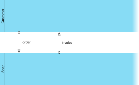
Before diving into the lines themselves, we must understand the containers they connect. The image displays two distinct Pools, represented by the large blue rectangular areas.
- Pool A (Customer): The top blue area represents the “Customer.” This is an external entity or a business partner.
- Pool B (Shop): The bottom blue area represents the “Shop.” This is the business being modeled.
These pools are separated by a boundary line. In BPMN, this boundary signifies an organizational or system border. It is crucial to remember that a single pool can contain multiple Lanes (internal departments), but communication across a pool boundary requires a different type of connector than communication within a pool.
Deep Dive: The Message Flow
The core subject of this diagram is the Message Flow. Visually, these are represented as dotted lines with arrows. Unlike the solid lines used for sequence flows, dotted lines indicate a dependency or communication that crosses the boundary between two participants.
How Message Flows Function
In the provided diagram, two specific message flows are illustrated:
- The “order” message: This flows from the Customer (Pool A) to the Shop (Pool B). The arrow points downward, indicating the initiation of a transaction.
- The “invoice” message: This flows from the Shop (Pool B) back to the Customer (Pool A). The arrow points upward, indicating the response or fulfillment.
These flows represent real-world communication channels. They are not necessarily direct function calls or database transactions; rather, they represent asynchronous or external interactions such as:
- Emails
- Phone calls
- System notifications
- Physical documents
The Critical Distinction: Sequence vs. Message
One of the most common errors in process modeling is confusing the internal flow of tasks with the external flow of messages. The image explicitly highlights the importance of this distinction.
Sequence Flow (Internal): If you were modeling the internal process of the “Shop” (e.g., “Receive Order” $\rightarrow$ “Process Payment” $\rightarrow$ “Send Invoice”), you would use a solid line with an arrow. This indicates that the second task happens immediately after the first one within the same system context.
Message Flow (External): Because the “order” originates from the Customer and the “invoice” is returned to them, these tasks occur in different pools. You cannot connect a task in the Customer pool directly to a task in the Shop pool with a solid line. You must use the dotted Message Flow.
This distinction ensures clarity. If a modeler uses a solid line between pools, it implies that the two pools are actually part of the same single system or process, which contradicts the architectural definition of distinct entities.
Visual Syntax Rules
When implementing this in a modeling tool like Visual Paradigm, the syntax follows strict rules to maintain the standard:
// Pseudo-logic for BPMN Diagram Structure

Pool Customer {
    // ... Internal Tasks ...
}

Pool Shop {
    // ... Internal Tasks ...
}

// The Connection (The Message Flow)
// Must use the 'dotted' style
connect(MessageFlow, CustomerPool, ShopPool);
setStyle(MessageFlow, style="dashed");
setLabel(MessageFlow, "order");

connect(MessageFlow, ShopPool, CustomerPool);
setStyle(MessageFlow, style="dashed");
setLabel(MessageFlow, "invoice");
Visual Paradigm Implementation
To recreate this architecture accurately, the industry-standard tool Visual Paradigm is widely used for its robust BPMN support.
When working within Visual Paradigm, you can utilize the specific tooling palette to add these elements:
- Create the Pools: Drag and drop two “Pool” objects onto the canvas. Rename them “Customer” and “Shop”.
- Select the Message Flow Tool: In the “Business Process” toolbar, locate the icon for the Message Flow. It is distinct from the Sequence Flow (which is usually a solid arrow) and the Association (which is a dotted line without an arrow).
- Connect the Pools: Click on a start event in the Customer pool and drag to a start event in the Shop pool. Visual Paradigm will automatically render the dotted line and the open circle/arrowhead terminator.
Conclusion
Understanding the difference between a sequence flow and a message flow is fundamental to creating professional BPMN diagrams. The image serves as a perfect example of how to model a transaction: the Customer sends an order (Message Flow) and receives an invoice (Message Flow), while the internal processing of these items happens within the Shop’s own sequence flows.
By adhering to these visual standards, you ensure that your architecture diagrams are not only aesthetically pleasing but also technically accurate and easily understood by stakeholders.

 English
 Arabic
 Chinese (Simplified)
 Dutch
Dutch French
 German
 Italian
 Japanese
 Korean
 Portuguese
 Russian
 Spanish