


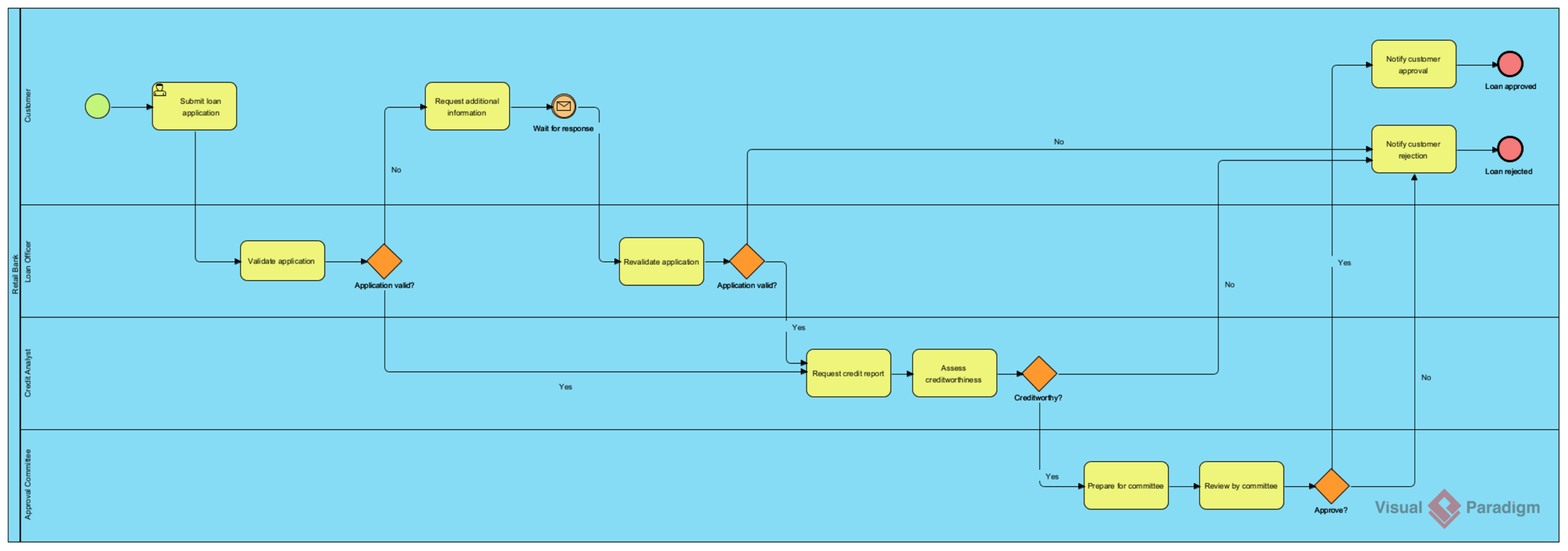
Welcome to this technical deep dive into Business Process Model and Notation (BPMN) 2.0. In the world of enterprise architecture, few challenges are as critical as visualizing complex workflows that involve multiple stakeholders. Today, we will analyze a comprehensive “Loan Application & Approval” process. This tutorial will not only break down the visual components of the diagram but also explain the underlying logic, the role of “Swimlanes,” and how to effectively model conditional flows using Visual Paradigm.
1. The Architecture of a Process: Understanding Swimlanes
The most striking feature of the diagram above is its vertical structure. In BPMN, these vertical partitions are known as Swimlanes. A swimlane is a visual way to organize the activities of a process by grouping them according to the participant responsible for performing them.
By using swimlanes, we achieve several architectural goals:
- Clarity of Responsibility: It immediately answers the question, “Who does what?”
- Handoff Visualization: It clearly shows where the process “hands off” from one department to another.
- Bottleneck Identification: It helps analysts see where work accumulates in a specific lane.
In our Retail Bank example, we see four distinct lanes:
- Customer: The external initiator of the process.
- Retail Bank (Loan Officer): The primary operational staff handling initial validation.
- Credit Analyst: A specialized role responsible for deep-dive financial assessment.
- Approval Committee: A governance body responsible for high-value or final decisions.
2. The Journey: Step-by-Step Process Logic
Let’s trace the flow of data and work from the top-left to the bottom-right. This flow is represented by the directed arrows connecting the shapes.
Phase 1: Initiation and Validation
The process begins with a Start Event (the green circle). The Customer performs the task “Submit loan application.” This task is an User Task, represented by the rounded rectangle with a small person icon, indicating manual work.
Once submitted, the flow moves down to the Retail Bank lane. The Loan Officer performs “Validate application.” This leads to a Exclusive Gateway (the orange diamond) asking: “Application valid?”
- Path A (No): If the application is incomplete, the process loops back up to the Customer via a “Request additional information” task.
- Path B (Yes): If valid, the flow continues to the Credit Analyst.
Phase 2: Assessment and Decision Making
The process enters the Credit Analyst lane. The analyst first “Request[s] credit report” and then performs the core analytical task: “Assess creditworthiness.” This culminates in another gateway: “Creditworthy?”
This is a critical decision point:
- If No, the flow moves right to the “Notify customer rejection” task.
- If Yes, the flow moves down to the Approval Committee.
Phase 3: Final Approval
In the final lane, the committee “Prepares for committee” and then conducts a “Review by committee.” This leads to the final decision gateway: “Approve?”
- No: The process ends with a rejection notification.
- Yes: The process ends with an approval notification and a End Event (the red circle).
3. Visual Paradigm Modeling Concepts
When implementing this architecture in Visual Paradigm, specific modeling choices are required to ensure the diagram adheres to industry standards.
Handling Transitions (Swimlane Crossing)
One of the most common errors in manual modeling is drawing lines that cut through swimlane boundaries arbitrarily. Visual Paradigm handles this elegantly:
- When a sequence flow leaves a lane (e.g., from Customer to Loan Officer), Visual Paradigm automatically calculates the intersection.
- The tool ensures that the sequence flow connects to the boundary of the receiving lane, rather than jumping to a random point inside it. This maintains the “container” integrity of the swimlane.
Gateways vs. Tasks
In Visual Paradigm, it is crucial to distinguish between a Task and a Gateway:
- Task (Yellow Rectangle): Represents work being done. It consumes resources.
- Gateway (Orange Diamond): Represents a decision point or a split/merge. It does not consume time or resources; it only controls the flow of tokens.
For example, in the “Application valid?” diamond, the system does not perform an action; it simply checks a condition and routes the token. In Visual Paradigm, you would typically use an Exclusive Gateway (XOR) for these binary decisions (Yes/No).
4. Best Practices for Complex Flows
When designing the “Request additional information” loop, notice how the flow returns to the Customer. This is a classic Re-entrant Flow. In Visual Paradigm, you can use the Sequence Flow tool to draw this back up. However, for complex loops, you might consider using an Intermediate Event (like the envelope icon shown in the “Wait for response” section) to indicate that the process is paused until an external trigger occurs.
Conclusion
The Loan Application process we analyzed demonstrates the power of BPMN 2.0. By combining visual symbols with a structured swimlane layout, we transform a complex, multi-departmental workflow into a readable, actionable map. Whether you are a business analyst or a software architect, mastering this notation is essential for defining clear system requirements and operational procedures.

 English
 Arabic
 Chinese (Simplified)
 Dutch
Dutch French
 German
 Italian
 Japanese
 Korean
 Portuguese
 Russian
 Spanish