


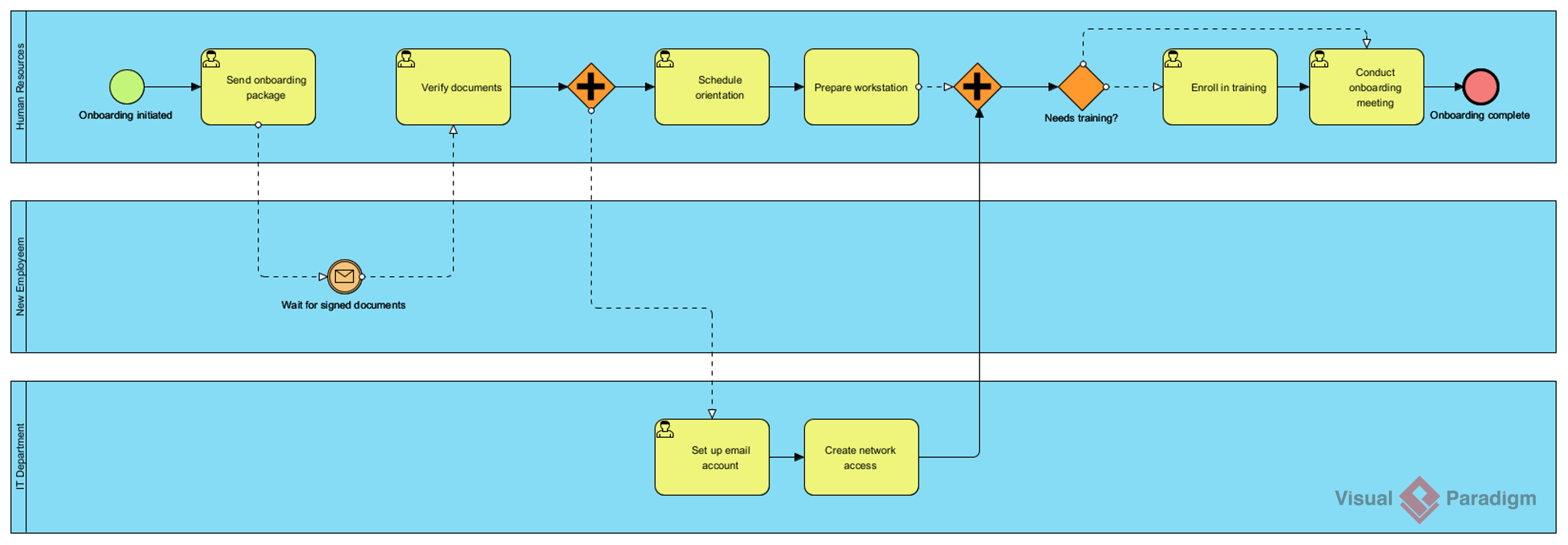
Business Process Model and Notation (BPMN) is the industry standard for visualizing business processes. Its true power lies in the Swimlane feature, which allows complex, multi-departmental workflows to be mapped clearly. This tutorial dissects a specific BPMN diagram depicting an Employee Onboarding Process, analyzing how Human Resources, IT, and New Employees interact within a mid-sized company environment.
We will deconstruct the flow from initiation to completion, examining the specific logic gates, parallel processing, and message flows that define a robust onboarding system. By understanding this architecture, you can replicate similar patterns for your own organizational workflows.
1. The Architecture of Swimlanes
The diagram utilizes a vertical swimlane structure to separate responsibilities. This is a critical concept in BPMN to prevent ambiguity regarding “who does what.”
- Human Resources (Top Lane): This lane acts as the primary process manager. It initiates the flow, handles documentation, and manages the final approval steps.
- New Employee (Middle Lane): This lane represents the participant receiving the service. It handles passive waiting periods and active receipt of training.
- IT Department (Bottom Lane): A support function lane. This demonstrates how backend departments are triggered without being the primary owners of the workflow.
2. Step-by-Step Process Analysis
Let’s trace the flow from the green start event to the red end event.
Initiation and Documentation (Sequential Flow)
The process begins with Onboarding Initiated. The HR representative immediately sends an onboarding package. A dashed line connects this task to the IT Department’s lane, indicating a dependency or data handoff, but the flow logically moves to the Verify documents task.
Parallel Processing (The Parallel Gateway)
Once documents are verified, the flow hits an Exclusive Gateway (the diamond with an “X”). This specific gateway serves as a trigger to split the process into two parallel branches. This is where the efficiency of the process is realized.
- Branch A (HR Side): HR proceeds to Schedule orientation and Prepare workstation.
- Branch B (New Employee Side): A dashed arrow with an envelope icon points to the New Employee lane. This is a Message Flow. The employee is notified to Wait for signed documents. This creates a “soft” dependency where the process waits for external input.
- Branch C (IT Side): Simultaneously, a dashed arrow triggers the IT Department. They execute Set up email account followed by Create network access.
Synchronization (Joining the Flows)
Notice the second gateway (the diamond with a “+” sign) in the HR lane. This is a Parallel Gateway (Join). It acts as a synchronization barrier. The process cannot proceed until all incoming paths are complete.
This ensures that HR does not proceed to the next stage until:
- They have prepared the workstation.
- The IT Department has finished setting up network access.
Conditional Logic (The Decision Gate)
After the synchronization, the process encounters an Exclusive Gateway (Diamond) labeled Needs training?. This introduces decision logic:
- Yes Path: If the employee requires training, the flow loops back to Enroll in training, then to Conduct onboarding meeting.
- No Path: If no training is needed, the flow bypasses the training steps entirely.
3. Key Technical Concepts in the Diagram
When modeling this scenario in Visual Paradigm, specific syntax rules apply to ensure the diagram renders correctly.
Message Flows vs. Sequence Flows
It is crucial to distinguish between the two types of connections used here:
- Sequence Flow (Solid Line): Represents the order of activities within the same swimlane or the main control flow. Example:
Prepare workstation->Join Gateway. - Message Flow (Dashed Line): Represents communication between two separate participants (swimlanes). Example:
Verify documents->Wait for signed documents.
Event-Based Gateways
The “Wait for signed documents” step is an Intermediate Catch Event (the envelope icon). It signifies a pause where the process is waiting for a specific message to arrive before resuming. This is distinct from a standard task because it implies a time gap and external interaction.
4. Implementation in Visual Paradigm
To replicate this architecture, follow these steps in the Visual Paradigm tool:
- Create Swimlanes: Go to the Process tab and select Add Swimlane. Label them “Human Resources”, “New Employee”, and “IT Department”.
- Draw Tasks: Use the User Task icon for steps like “Send onboarding package”.
- Connect with Gateways: Drag an Exclusive Gateway (X) to split the flow and a Parallel Gateway (+) to synchronize it.
- Apply Message Flow: Switch your connection tool to Message Flow (usually dashed) to connect tasks across the horizontal lines.
Conclusion
This onboarding process demonstrates a sophisticated use of BPMN to handle asynchronous tasks. By utilizing parallel gateways and message flows, the diagram ensures that the IT and HR departments work in sync without unnecessary bottlenecks. This structure is essential for mid-sized companies where resource efficiency is critical.

 English
 Arabic
 Chinese (Simplified)
 Dutch
Dutch French
 German
 Italian
 Japanese
 Korean
 Portuguese
 Russian
 Spanish