


In the rapidly evolving landscape of software development and systems engineering, the separation of “writing” and “modeling” has historically created friction. Teams often write requirements in one tool, create diagrams in another, and manage versions in a third. This fragmentation leads to the “single source of truth” problem, where stakeholders are unsure if the diagram matches the text.
OpenDocs, a platform integrated with Visual Paradigm’s ecosystem, attempts to solve this by creating a unified Knowledge Tree. This tutorial breaks down the system architecture of this hybrid platform, exploring how it integrates textual documentation with high-level visual modeling (specifically BPMN and UML) into a single, navigable hierarchy.
The Core Architecture: The Knowledge Tree
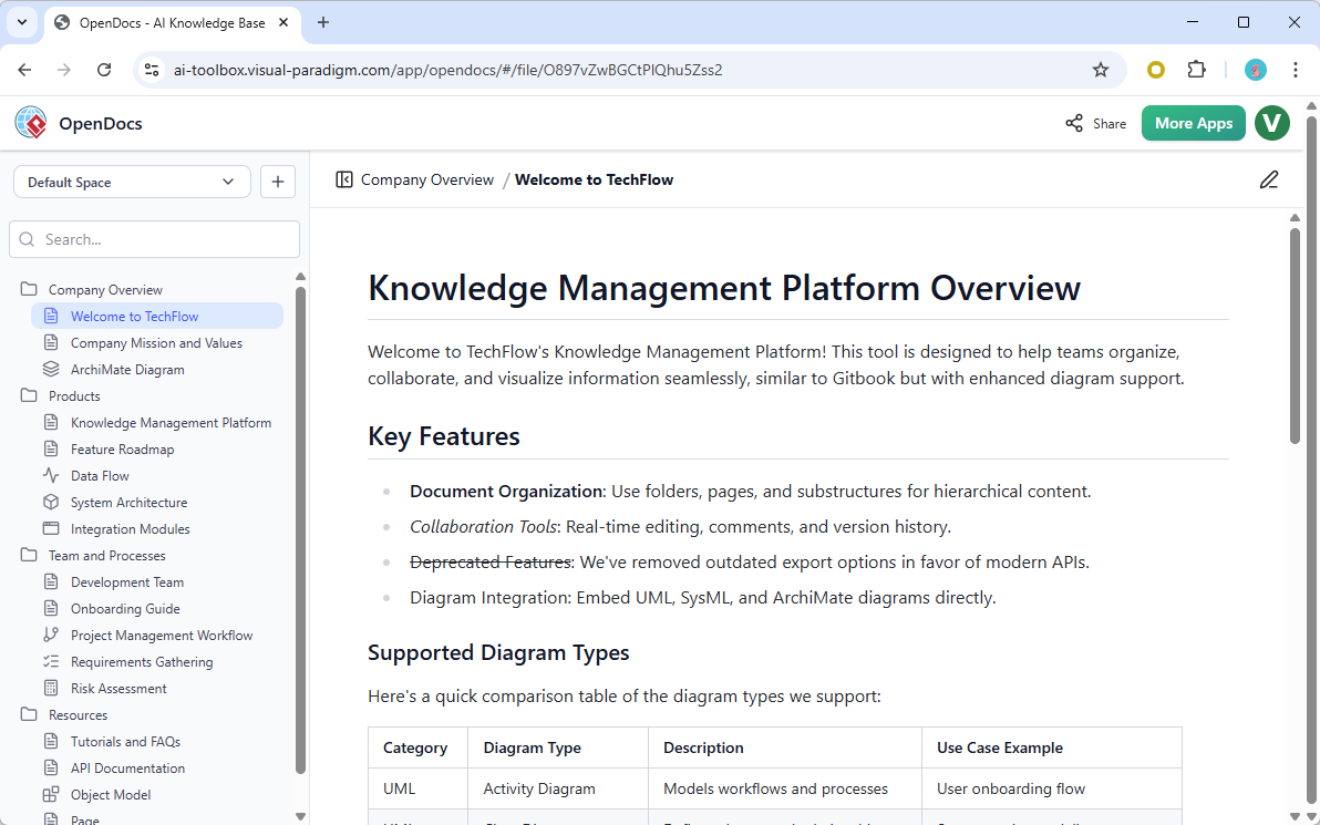
The most distinct feature of OpenDocs is its interface structure, which mimics a file system but functions as a semantic knowledge graph. This is known as the Knowledge Tree. Unlike a standard folder structure (like a Windows Explorer window), the Knowledge Tree is designed to grow with the project lifecycle.
1. The Hierarchical Structure
The left-hand navigation panel represents the backbone of the documentation. It allows for:
- Logical Grouping: Concepts are grouped by context (e.g., “Company Overview,” “Products,” “Team and Processes”).
- Nested Levels: You can drill down from high-level strategy to granular technical specs. For example, a “Products” folder might contain a “Knowledge Management Platform,” which further contains “Feature Roadmap.”
- File Type Agnostic: The tree accepts both static text documents (like a “Welcome to TechFlow” page) and dynamic diagram files (like an “ArchiMate Diagram” or “Data Flow”).
2. The Viewport (Canvas)
The main area of the interface serves as the viewport. When you click a node in the Knowledge Tree, the viewport renders the content. If you select a text page, you see rich text editing. If you select a diagram file, the viewport loads the rendering engine for that specific diagram type (e.g., BPMN, UML).
Integrating Modeling: BPMN and AI
OpenDocs is not just a wiki; it is a modeling environment. The “Supplementary note” regarding Visual Paradigm BPMN + AI Assisted suggests a powerful workflow for process modeling.
Business Process Model and Notation (BPMN)
BPMN is the industry standard for visualizing business processes. In OpenDocs, this is integrated directly into the knowledge tree. Instead of exporting a PNG image of a process and pasting it into a Word document, the actual model lives inside the tree.
This means:
- Dynamic Validation: The diagram remains a live object. If you change a process step, the underlying data updates.
- Traceability: You can link specific text requirements to specific shapes in the BPMN diagram.
The AI Factor
The mention of “AI Assisted” tooling implies that OpenDocs likely utilizes Large Language Models (LLMs) to:
- Auto-Generate Diagrams: A user might type a requirement like “User logs in, then checks inventory,” and the AI generates the corresponding BPMN flowchart.
- Natural Language Queries: Users might ask the system, “Where is the API integration documented?” and the system navigates the Knowledge Tree to the specific page.
Step-by-Step: Building a Unified Knowledge Base
Let’s walk through the conceptual workflow of using OpenDocs to build a system specification.
Step 1: Define the Space
Start by establishing a Space (e.g., “Company Overview”). This acts as the root container for your project. In the screenshot, we see the “Default Space” selected.
Step 2: Create the Hierarchy
Use the + button next to the Space name to create a new folder. Let’s name it “System Architecture.” This folder will hold your technical diagrams.
Step 3: Embed the Model
Inside the “System Architecture” folder, create a new item. Instead of a text file, select a diagram type (e.g., BPMN or UML Class Diagram). Visual Paradigm’s engine will render the editor within the browser.
Step 4: Link Text and Visuals
This is the “magic” mentioned in the context. In the text editor, you can type: “The login process is defined in the diagram below.” Then, you link the “Login BPMN” file directly. The user can now toggle between reading the spec and viewing the diagram without leaving the page.
graph TD
    A[User] --> B{Login?}
    B -- Yes --> C[Dashboard]
    B -- No --> D[Error Message]

    style A fill:#f9f,stroke:#333,stroke-width:2px
    style C fill:#bbf,stroke:#333,stroke-width:2px
Figure 1: A simplified example of how logical flow (like a login process) might be represented as a model within the system.
Key Features Breakdown
Based on the interface provided, here are the critical architectural components:
- Real-Time Collaboration: The “Share” button indicates multi-user editing capabilities. This is essential for teams where architects and developers need to update the “Knowledge Tree” simultaneously.
- Search Functionality: The “Search…” bar at the top of the sidebar allows for full-text search across the entire Knowledge Tree, ensuring that documentation is discoverable.
- Integrated Tooling: The “More Apps” button suggests a modular architecture where OpenDocs can extend its capabilities with additional plugins (e.g., specific AI models or export tools).
Conclusion
OpenDocs represents a shift from “document repositories” to “knowledge environments.” By merging the linear nature of text with the spatial nature of diagrams, and backing it with the robust modeling engine of Visual Paradigm, it offers a single pane of glass for complex technical projects. Whether you are mapping out a BPMN workflow or writing a system requirement, the Knowledge Tree ensures that your visual and textual assets remain synchronized.

 English
 Arabic
 Chinese (Simplified)
 Dutch
 French
 German
 Italian
 Japanese
 Korean
 Portuguese
 Russian
 Spanish