


With AI-Powered Generation Features & Best Practices
🎯 Introduction
Composite Structure Diagram is one of the new artifacts added to UML 2.0. A composite structure diagram is a UML structural diagram that contains classes, interfaces, packages, and their relationships, and that provides a logical view of all, or part of a software system. It shows the internal structure (including parts and connectors) of a structured classifier or collaboration.
A composite structure diagram performs a similar role to a class diagram, but allows you to go into further detail in describing the internal structure of multiple classes and showing the interactions between them. You can graphically represent inner classes and parts and show associations both between and within classes.
💡 Pro Tip: Use Composite Structure Diagrams when you need to “peek inside” complex objects to understand their runtime composition and internal collaborations.
🚀 Learn UML Faster, Better and Easier
Are you looking for a Free UML tool for learning UML faster, easier and quicker? Visual Paradigm Community Edition is a UML software that supports all UML diagram types. It is an international award-winning UML modeler, and yet it is easy-to-use, intuitive & completely free.
📋 Purpose of Composite Structure Diagram
-
Peek Inside Objects: Composite Structure Diagrams allow the users to “Peek Inside” an object to see exactly what it is composed of.
-
Detail Internal Actions: The internal actions of a class, including the relationships of nested classes, can be detailed.
-
Composition Modeling: Objects are shown to be defined as a composition of other classified objects.
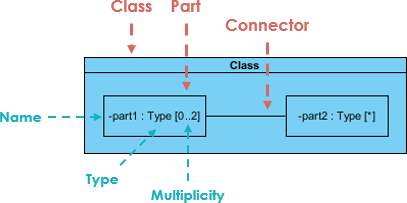
🔍 Composite Structure Diagram at a Glance
-
Composite Structure Diagrams show the internal parts of a class.
-
Parts are named:
partName:partType[multiplicity] -
Aggregated classes are parts of a class but parts are not necessarily classes—a part is any element that is used to make up the containing class.
🔄 Deriving Composite Structure Diagram from Class Diagram
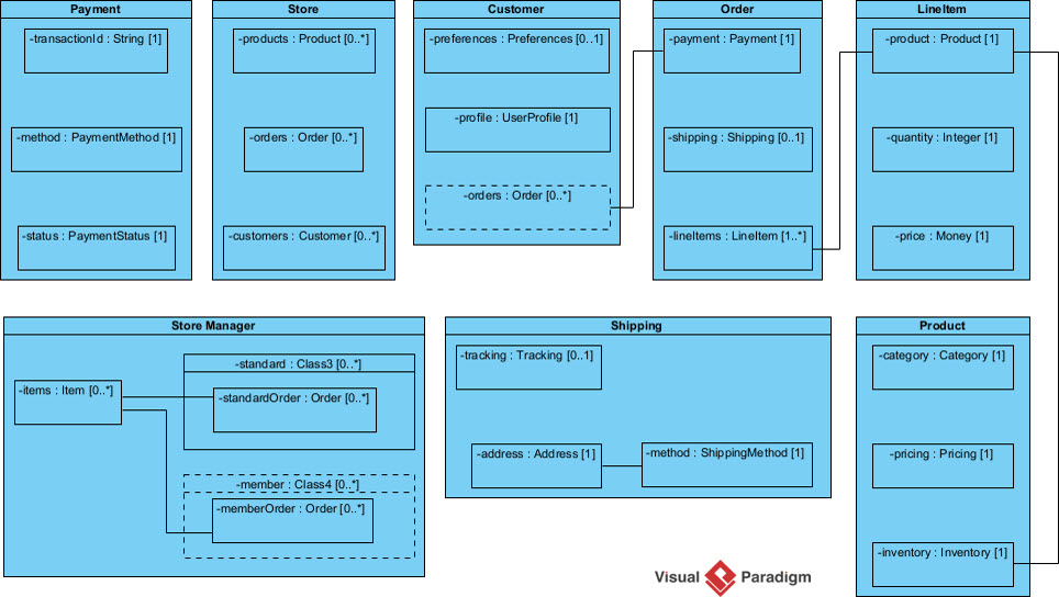
Case Study: Online Store
Suppose we are modeling a system for an online store. The client has told us that customers may join a membership program which will provide them with special offers and discounted shipping, so we have extended the customer object to provide a member and standard option.
Let’s model the online store using a class diagram:
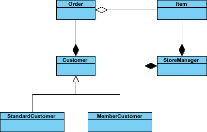
We have a class for Item which may be aggregated by the Order class, which is composed by the Customer class which itself is composed by the StoreManager class. We have a lot of objects that end up within other objects.
Everything looks like it ends up inside StoreManager, so we can create a composite structure diagram to really see what it’s made of.
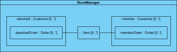
Key Insights from the Example:
-
StoreManager perspective: Viewed from its own perspective, instead of the system as a whole.
-
Direct containment: StoreManager directly contains two types of objects (Customer and Item) as indicated by the two composition arrows on the class diagram.
-
Subtype visibility: The composite structure diagram shows more explicitly the inclusion of the subtypes of Customer.
-
Type consistency: Notice that the type of both of these parts is Customer, as the store sees both as Customer objects.
-
Connector relationships: We see a connector which shows the relation between Item and Order.
-
Nested relations: Order is not directly contained within the StoreManager class but we can show relations to parts nested within the objects it aggregates.
⚖️ Class Diagram vs. Composite Structure Diagram
Question: Are two diagram below expressing the same meaning?
Answer: In a class diagram the reference between Description and Pricing is ambiguous; strictly speaking, they are not exactly the same.
-
The class diagram does show that Description will have a reference to a Pricing object
-
But it does not specify whether the reference between the two objects is contained inside the item explicitly
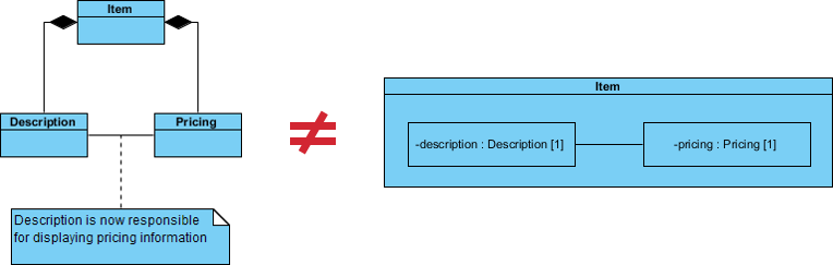
Why Choose Composite Structure Diagram?
If we use a Composite Structure Diagram, the meaning of the containment of the association relationship is unambiguous:
-
✅ The reference between the Description and Pricing objects is contained to objects that are composed by Item.
-
✅ The specific implementations of an object’s activity can be clearly modeled.
-
✅ Runtime structure and internal collaborations become explicit.
🔗 References to External Parts
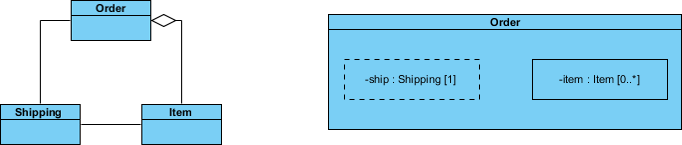
We have seen examples of how Composite Structure diagrams are great at describing aggregation, but your models will also need to contain references to objects outside of the class you are modeling.
But what about referencing an external object with Composite Structure Diagram like the example below?
Best Practices for External References:
-
🔹 References to external objects are shown as a part with a dashed rectangle.
-
🔹 Even though the referenced object is outside of the class, the reference itself is within the modeled class and is an important step in showing its implementation.
-
🔹 Use clear naming conventions to distinguish internal parts from external references.
🧩 Basic Concepts of Composite Structure Diagram
The key composite structure entities identified in the UML 2.0 specification are structured classifiers, parts, ports, connectors, and collaborations.
🤝 Collaboration
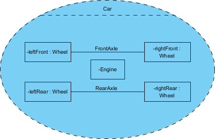
A collaboration describes a structure of collaborating parts (roles). A collaboration is attached to an operation or a classifier through a Collaboration Use. You use a collaboration when you want to define only the roles and connections that are required to accomplish a specific goal of the collaboration.
For example, the goal of a collaboration can be to define the roles or the components of a classifier. By isolating the primary roles, a collaboration simplifies the structure and clarifies behavior in a model.
Example: In this example the Wheels and the Engine are the Parts of the Collaboration and the FrontAxle and the RearAxle are the Connectors. The Car is the Composite Structure that shows the parts and the connections between the parts.
🧱 Parts
A part is a diagram element that represents a set of one or more instances that a containing structured classifier owns. A part describes the role of an instance in a classifier. You can create parts in the structure compartment of a classifier, and in several UML diagrams such as composite structure, class, object, component, deployment, and package diagrams.
🔌 Port
A port defines the interaction point between a classifier instance and its environment or between the behavior of the classifier and its internal parts.
🎨 Interface
Composite Structure diagram supports the ball-and-socket notation for the provided and required interfaces. Interfaces can be shown or hidden in the diagram as needed.
🔗 Connector
A line that represents a relationship in a model. When you model the internal structure of a classifier, you can use a connector to indicate a link between two or more instances of a part or a port. The connector defines the relationship between the objects or instances that are bound to roles in the same structured classifier and it identifies the communication between those roles. The product automatically specifies the kind of connector to create.
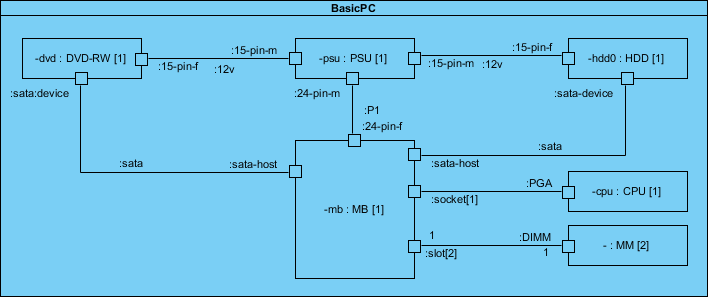
💻 Composite Structure Diagram Example – Computer System
Let’s develop the composite structure diagram for a computer system which includes the following components:
-
Power Supply Unit (PSU)
-
Hard Disk Drive (HDD)
-
Mainboard (MB)
-
Optical Drive (DVD-RW)
-
Memory Module (MM)
We will assume for the moment that the mainboard is of the type that has a sound card and display adapter built in:
Modeling Tips for This Example:
-
Use clear part names that reflect runtime roles (e.g.,
primaryStorage:HDD[1]) -
Show connectors between parts that actually communicate at runtime
-
Use ports on the Mainboard to represent expansion slots and interfaces
-
Consider multiplicity for scalable components (e.g.,
memorySlot:MM[0..4])
🎨 Draw Composite Structure Diagram Now
You’ve learned what a Composite Structure Diagram is and how to draw a Composite Structure Diagram. It’s time to draw a Composite Structure Diagram of your own. Get Visual Paradigm Community Edition, a free UML software, and create your own Composite Structure Diagram with the free Composite Structure Diagram tool. It’s easy-to-use and intuitive.
🤖 New: Generate AI Composite Structure Diagrams in Visual Paradigm Desktop
March 25, 2026
EDITION REQUIRED | DESKTOP Professional
We are excited to announce a powerful update to Visual Paradigm Desktop. Our latest release introduces the ability to generate professional Composite Structure Diagrams using advanced AI technology. This new feature streamlines the modeling of internal structures, ports, and collaborations, making us a leading AI UML tool for modern software architects.
Whether you are documenting complex system hierarchies or detailing the runtime interactions of a microservice, our AI UML generator allows you to transform a simple text description into a structured visual model in seconds.
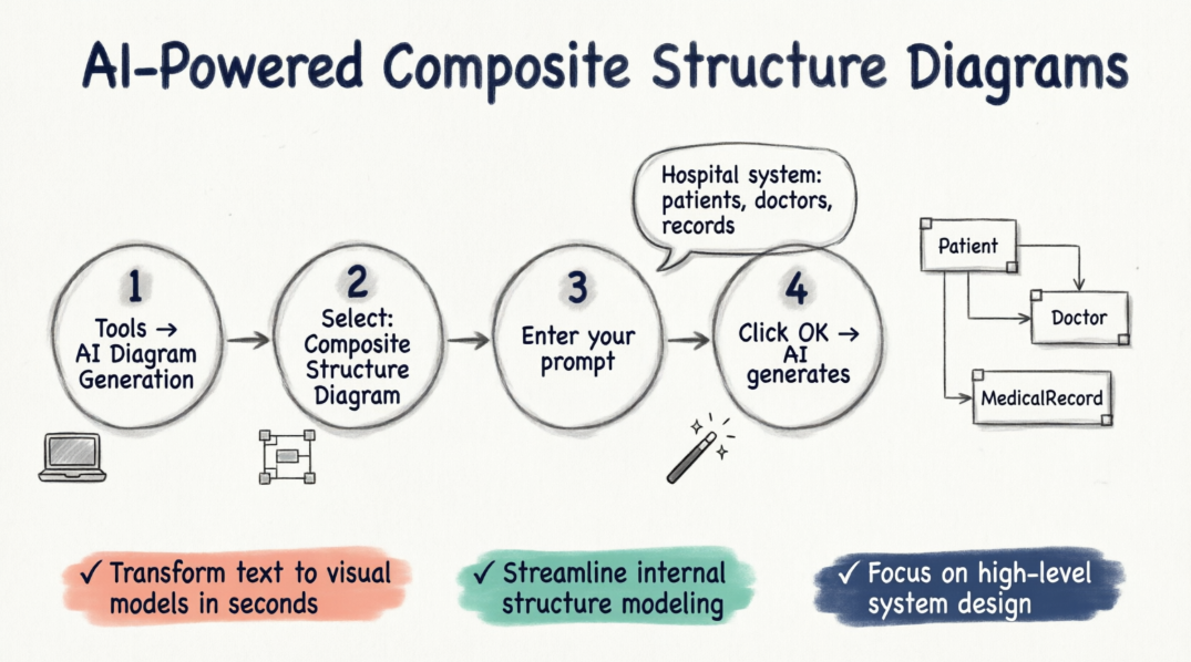
How to Use the AI Composite Structure Diagram Generator
Creating your next diagram is a seamless process within the desktop environment. Follow these four simple steps to get started:
-
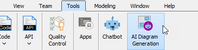
Navigate to the top menu and select Tools > AI Diagram Generation. This will open the AI Diagram Generation dialog box.
-
In the diagram type selection, choose Composite Structure Diagram.
-
Enter your specific topic or requirements. For example: “Generate a Composite Structure Diagram for a hospital management system illustrating relationships between patients, doctors, and medical records.”
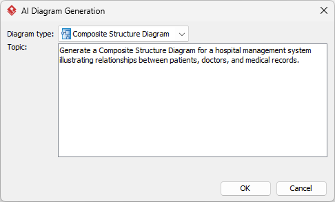
-
Click OK.
Once the AI processes your request, it will generate the resulting diagram directly on your canvas. From there, you can continue modeling, revise the components, or fine-tune the layout using our comprehensive suite of UML tools.
This update reinforces our commitment to being the most versatile AI diagram generator on the market. By integrating AI into the UML workflow, we help teams reduce manual effort and focus on high-level system design. You can explore more about how this works on our AI diagram generation landing page.
Ready to accelerate your modeling workflow?
Experience the most advanced AI UML generator available today.
Download Visual Paradigm Desktop
We look forward to seeing the complex systems you build with our new AI-driven capabilities. Stay tuned for more updates as we continue to expand our AI toolkit.
🧠 AI-Powered Composite Structure Diagram Generation
Visual Paradigm’s AI can generate UML Composite Structure Diagrams directly from natural language descriptions, allowing you to visualize the internal structure of classes, components, or systems without manual drawing. [1, 2]
How to Generate a Composite Structure Diagram with AI
You can use this feature in either the Desktop application or the Online “OpenDocs” workspace. [3]
Option 1: Using Visual Paradigm Desktop
-
Open the Tool: Navigate to the top menu and select Tools > AI Diagram Generation.
-
Select Diagram Type: In the dialog box, choose Composite Structure Diagram from the dropdown menu.
-
Enter Your Prompt: Provide a specific topic or architectural requirement (e.g., “Generate a Composite Structure Diagram for a hospital management system showing the relationship between doctors and medical records”).
-
Generate: Click OK. The AI will process the text and render the diagram directly on your canvas. [2, 4, 5, 6]
Option 2: Using Visual Paradigm Online (OpenDocs)
-
Open Editor: Inside an OpenDocs Space, click the Insert button in the top bar and select the Diagrams tab.
-
Choose Diagram: Select Composite Structure Diagram to open the editor.
-
Use AI: Click Create with AI at the top right of the editor.
-
Describe & Render: Enter your system description in the input box and click Generate. [1]
Refinement and Customization
Once the initial diagram is created, you can refine it conversationally using the AI Chatbot: [7, 8, 9]
-
🔧 Modify Elements: Ask the bot to “Rename Guest contact info to Contact” or “Add a new part for Payment Gateway”.
-
🔗 Establish Links: Instruct it to “Create a connector between Booking Details and Room”.
-
📊 Traceability: The AI can cross-reference your existing Class Diagrams to ensure the internal parts and ports remain consistent with your broader model. [10, 11, 12, 13, 14]
💬 Do you have a specific system architecture in mind that you would like a prompt for?
💡 User Experience Sharing: Feature Review, Guidelines & Tips
🌟 Real-World User Feedback
“The AI generator saved me hours on our microservices architecture documentation. I described our payment processing flow in plain English, and within seconds I had a clean composite structure diagram showing all the internal components and their connectors. The ability to then refine it conversationally with the AI chatbot was a game-changer.”
— Sarah K., Senior Software Architect
“As a team lead, I appreciate how the AI helps junior developers understand complex internal structures. We start with an AI-generated diagram, then collaboratively refine it. It’s become our onboarding standard for new system modules.”
— Marcus T., Engineering Manager
🎯 Best Practices & Guidelines
✅ When to Use Composite Structure Diagrams
| Scenario | Recommendation |
|---|---|
| Modeling runtime object composition | ✅ Ideal |
| Showing internal collaborations between parts | ✅ Ideal |
| Documenting port-based interactions | ✅ Ideal |
| Simple class relationships | ⚠️ Use Class Diagram instead |
| High-level system architecture | ⚠️ Use Component/Deployment Diagram |
🛠️ Modeling Tips & Tricks
-
Start Simple, Then Expand
-
Begin with core parts and essential connectors
-
Add ports and interfaces incrementally
-
Use collaborations to isolate specific interaction patterns
-
-
Naming Conventions Matter
Format: partName:partType[multiplicity] Example: primaryDatabase:PostgreSQL[1] Example: cacheNode:Redis[0..3] -
Use Ports for Clear Interfaces
-
Define explicit interaction points
-
Attach provided/required interfaces using ball-and-socket notation
-
Document protocol expectations in port documentation
-
-
Leverage AI Prompts Effectively
❌ Weak: "Show me a system diagram" ✅ Strong: "Generate a Composite Structure Diagram for an e-commerce checkout service showing internal parts: PaymentProcessor, InventoryValidator, ShippingCalculator, and their connectors with ports for external API interactions" -
Maintain Traceability
-
Link parts back to class definitions
-
Use stereotypes to indicate implementation details
-
Keep diagrams synchronized with code via model-driven engineering
-
🚫 Common Pitfalls to Avoid
| Pitfall | Solution |
|---|---|
| Over-complicating with too many parts | Focus on runtime-relevant components only |
| Confusing parts with classes | Remember: parts are roles instances play within a composite |
| Ignoring multiplicity | Always specify [1], [0..*], etc., for clarity |
| Missing connector semantics | Label connectors with interaction protocols or message types |
| Forgetting external references | Use dashed rectangles for external object references |
🔄 Iterative Refinement Workflow

graph LR
    A[Text Prompt] --> B[AI Generation]
    B --> C[Initial Diagram]
    C --> D[AI Chatbot Refinement]
    D --> E[Manual Fine-Tuning]
    E --> F[Validation & Export]
    F --> G[Documentation/Code Gen]
- 🔗 Reference
- AI Composite Structure Diagram Generator for OpenDocs: Announcement and guide for generating Composite Structure Diagrams using AI in Visual Paradigm’s online OpenDocs workspace.
- AI Composite Structure Diagram Generator for Desktop: Release notes detailing the AI-powered Composite Structure Diagram generation feature for Visual Paradigm Desktop Professional edition.
- AI UML Generator for Beginners Guide: Beginner-friendly tutorial covering how to use Visual Paradigm’s AI tools to generate various UML diagrams, including Composite Structure Diagrams.
- AI Composite Structure Diagram Generator for Desktop: Duplicate reference to the desktop AI generator release announcement with implementation details and use cases.
- Visual Paradigm AI Diagram Generation Tutorial (YouTube): Video tutorial demonstrating step-by-step how to use Visual Paradigm’s AI features to generate and refine UML diagrams.
- Enhance Design Thinking: New AI Diagram Generation: Blog post discussing how AI diagram generation integrates into design thinking workflows and accelerates system modeling.
- Miro AI Diagram Creation Overview: Comparative resource discussing AI-powered diagram automation principles applicable to UML modeling tools.
- UML Class Diagram Tutorial with AI Chatbot: Tutorial showing how Visual Paradigm’s AI Chatbot can draft and refine UML diagrams through conversational interaction.
- Visual Paradigm AI Features Demo (YouTube): Video demonstration of Visual Paradigm’s AI capabilities including diagram generation, refinement, and chatbot interaction.
- Visual Paradigm AI Chatbot Features: Product page detailing the AI Chatbot functionality for conversational diagram creation and refinement across UML diagram types.
- Advanced AI Modeling Techniques (YouTube): Advanced tutorial covering sophisticated uses of AI for complex system modeling and diagram traceability.
- Advanced AI Modeling Techniques (YouTube): Duplicate reference to advanced AI modeling video tutorial.
- AI-Powered Composite Structure Diagram Guide: Comprehensive documentation for using AI to model internal structures, parts, ports, and collaborations in Composite Structure Diagrams.
- AI-Powered Object Diagram Guide: Related guide on using AI for Object Diagrams, which complement Composite Structure Diagrams for runtime instance visualization.
-
🏁 Final Thought: Composite Structure Diagrams bridge the gap between static class definitions and dynamic runtime behavior. With AI-powered generation tools, you can now create, refine, and maintain these complex diagrams faster than ever—freeing you to focus on architecture, not drawing. Start small, iterate often, and let AI handle the heavy lifting.
- Happy Modeling! 🎨✨
