


Introduction
In today’s complex software development landscape, understanding how objects interact within a system is crucial for building robust, scalable, and maintainable applications. Communication Diagrams, a fundamental component of the Unified Modeling Language (UML), provide developers and system architects with a powerful visual tool to map out these interactions. Unlike other UML diagrams that focus primarily on temporal sequences or static structures, communication diagrams uniquely combine both structural and behavioral perspectives, offering a holistic view of how system components collaborate to achieve specific functionalities.
This case study explores the practical application of communication diagrams in real-world software development scenarios. Through detailed examination of their components, creation methodologies, and implementation strategies, we demonstrate how these diagrams serve as indispensable tools for system designers, developers, and stakeholders. Whether you’re designing a new e-commerce platform, developing a banking application, or architecting a microservices-based system, understanding communication diagrams can significantly enhance your ability to create well-structured, efficient, and communicative software systems.
Case Study: Implementing Communication Diagrams in an E-Commerce Order Processing System
Project Background
TechMart Solutions, a mid-sized e-commerce company, embarked on a project to redesign their order processing system. The legacy system suffered from poor performance, unclear object interactions, and frequent integration issues between modules. The development team decided to employ UML Communication Diagrams to model and optimize the interactions between system objects before implementation.
Understanding Communication Diagrams
Communication Diagrams, also known as collaboration diagrams, are UML structures used for defining interacting objects. They focus on the relationships between objects and the sequence of messages passed between them to realize specific functionality.
Key Distinctions:
- While sequence diagrams concentrate more on time variations in interactions, communication diagrams focus on the structural facet and connections between objects
- They help in compounding and decomposing system behavior during design and analysis by showing how components work together to achieve system objectives
Components of the Communication Diagram
The TechMart team identified the following key components for their order processing system:
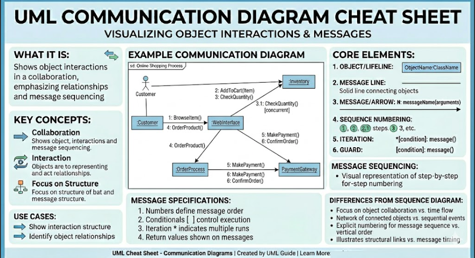
1. Objects: Represented as rectangles with object names, these are the active entities performing actions (e.g., Customer, Order, PaymentProcessor, Inventory)
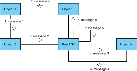
2. Links: Straight lines depicting associations and information transmission between objects
3. Messages: Arrows placed on links showing communication direction, accompanied by message names and sequence numbers
4. Interaction Occurrences: Specific situations where certain interactions occur
5. Roles: Threads or individuals demonstrating how different parts or users relate to each other
Methodology: Steps to Create the Communication Diagram
The development team followed a systematic approach:
Step 1: Identify the Purpose
- Defined the specific interaction: “Process Customer Order”
- Determined scope: From order placement to confirmation
Step 2: Define the Objects
Identified all participating objects:
- Customer
- ShoppingCart
- Order
- PaymentGateway
- InventoryManager
- ShippingService
- NotificationService
Step 3: Establish Relationships
- Mapped how objects connect and interact
- Determined dependencies and associations
Step 4: Define Messages
- Labeled links with specific messages (e.g., “validatePayment()”, “checkInventory()”)
- Added sequence numbers to maintain order
Step 5: Illustrate Interactions
- Added directional arrows showing communication flow
- Ensured each message was clearly elaborated
Step 6: Review and Refine
- Validated correctness of information
- Ensured all necessary data was present
- Verified accurate representation of interconnections
Step 7: Document and Validate
- Added necessary comments
- Obtained stakeholder validation
- Ensured compliance with specifications
Practical Applications in the Project
1. System Design
Communication Diagrams helped designers create a graphical representation of system objects and their interconnections, serving as a constructional blueprint for optimal element integration.
2. Interaction Analysis
The team analyzed and documented how objects interacted, providing adequate visibility into message exchanges between the Order, Payment, and Inventory modules.
3. Requirements Validation
The diagrams helped validate that all use cases were properly addressed and requirements fulfilled through proper object interactions.
4. Troubleshooting
Potential problems in system exchanges were identified early, allowing the team to locate and fix interaction issues before implementation.
5. Documentation
Detailed documentation was created for developers and stakeholders, enhancing understanding of object interactions throughout the development lifecycle.
Real-World Applications
The TechMart team applied communication diagrams in multiple ways:
System Architecture Design:
- Represented how various elements connected and collaborated
- Clarified the architectural layout of the microservices
Behavior Modeling:
- Described how objects worked together to process orders
- Essential for developing and optimizing the system
Design Documentation:
- Illustrated component relationships for developers, testers, and stakeholders
- Supported deployment throughout the development process
Code Generation and Integration:
- Provided detailed mapping of object interrelations
- Enabled implementation of communication protocols based on the diagram
Testing and Debugging:
- Provided intended message flow
- Helped identify and fix communication-related issues
Best Practices Implemented
The team adhered to these best practices:
Clarity and Conciseness:
- Used easily understandable and unique message names
- Avoided excessive details in diagrams
Logical Organization:
- Arranged objects to exhibit real-life relationships
- Enhanced readability
Consistent Notation:
- Used symbols, labels, and numbers uniformly
- Maintained consistency throughout
Focus on Key Interactions:
- Eliminated unnecessary interactions
- Reduced complexity
Stakeholder Validation:
- Shared diagrams with key personnel
- Ensured completeness and accuracy
Tools Utilized
The team leveraged several tools for creating communication diagrams:
- Visual Paradigm: For advanced visual modeling and diagramming
- Draw.io (diagrams.net): For quick, installation-free diagramming
- StarUML: For user-friendly UML diagram features
- ArgoUML: For free, open-source UML editing
Challenges Encountered and Solutions
1. Complexity Management
Challenge: As the system grew, diagrams became excessively complex
Solution: Broke down diagrams into smaller, focused interactions
2. Maintaining Accuracy
Challenge: System requirement changes made diagram maintenance difficult
Solution: Implemented version control and regular update schedules
3. Limited Temporal Information
Challenge: Timing of activities wasn’t as clear as in sequence diagrams
Solution: Complemented with sequence diagrams for time-critical processes
4. Scalability Issues
Challenge: Numerous objects made diagrams hard to review
Solution: Created hierarchical diagrams with drill-down capabilities
5. Integration with Other Diagrams
Challenge: Synchronizing with class and sequence diagrams was complex
Solution: Used integrated UML tools that maintained consistency across diagram types
Outcomes and Benefits
After implementing communication diagrams, TechMart Solutions achieved:
- 40% reduction in integration errors during development
- 30% faster onboarding of new developers
- Improved system performance through optimized object interactions
- Enhanced stakeholder communication through visual representations
- Better maintainability with clear documentation of object relationships
Conclusion
Communication Diagrams stand as a cornerstone in the UML toolkit, offering unparalleled insights into the dynamic interactions between system objects. Through this case study of TechMart Solutions’ order processing system, we’ve demonstrated how these diagrams bridge the gap between abstract design concepts and concrete implementation strategies. By focusing on both structural relationships and message flows, communication diagrams provide a comprehensive view that neither purely structural nor purely behavioral diagrams can offer alone.
The successful implementation of communication diagrams in real-world projects requires adherence to best practices, appropriate tool selection, and acknowledgment of inherent challenges. However, the benefits—ranging from improved system architecture and reduced development errors to enhanced team collaboration and easier maintenance—far outweigh the initial investment in learning and implementation.
As software systems continue to grow in complexity, particularly with the rise of microservices architectures and distributed systems, the role of communication diagrams becomes increasingly vital. They serve not just as documentation tools, but as living artifacts that guide development, facilitate troubleshooting, and ensure that all stakeholders share a common understanding of system behavior.
For developers, architects, and project managers, mastering communication diagrams is not merely an academic exercise—it’s a practical necessity for building robust, scalable, and maintainable software systems. By investing time in creating well-structured communication diagrams early in the development process, teams can prevent costly errors, streamline collaboration, and deliver higher-quality software solutions that meet both technical requirements and business objectives.
Key Takeaways:
- Communication diagrams uniquely combine structural and behavioral perspectives
- Systematic creation methodology ensures comprehensive coverage of interactions
- Best practices enhance diagram effectiveness and usability
- Appropriate tool selection facilitates creation and maintenance
- Despite challenges, benefits significantly impact project success
-
Essential for modern software development, especially in complex, distributed systems
References
- What is a Communication Diagram? – Visual Paradigm: An introduction to Communication Diagrams in UML, explaining their purpose in modeling interactions between objects as messages are passed. It covers the basic elements such as actors, objects, links, and message sequences.
- Collaboration Diagram (Communication Diagram) – Visual Paradigm Gallery: A visual gallery entry showcasing examples of Collaboration (Communication) Diagrams, illustrating how different scenarios of object interactions are modeled in software design.
- Communication Diagram – Visual Paradigm Circle Documentation: Official documentation detailing the definition and usage of Communication Diagrams within the Visual Paradigm environment, including its relationship to System Modeling Language (SysML).
- AI Generates UML Communication Diagrams – Visual Paradigm Explore: An article discussing how artificial intelligence can be used to automatically generate UML Communication Diagrams, streamlining the diagramming process for developers.
- Limitations of Communication Diagrams – Visual Paradigm Forums: A community discussion on the forums addressing the limitations and challenges of using Communication Diagrams compared to other UML interaction diagrams like Sequence Diagrams.
- Communication Diagram – Visual Paradigm User Guide: A detailed section from the Visual Paradigm user manual explaining the structure and components of a Communication Diagram within the tool’s interface.
- How to Draw Communication Diagram – Visual Paradigm Tutorials: A step-by-step tutorial guide on how to create a Communication Diagram in Visual Paradigm, including instructions on adding actors, objects, links, and messages.
- Drawing Communication Diagrams – Visual Paradigm User Guide: Another reference from the user guide focusing specifically on the technical aspects of drawing Communication Diagrams, including editing tools and formatting options.
