


Introduction
In today’s rapidly evolving software development landscape, capturing clear, actionable requirements remains one of the most critical—and challenging—phases of any project. Misunderstood requirements lead to scope creep, rework, delayed deliveries, and ultimately, products that fail to meet user expectations. Enter the Use Case Diagram: a deceptively simple yet profoundly powerful visual modeling technique within the Unified Modeling Language (UML) that bridges the gap between stakeholder needs and technical implementation.

This comprehensive case study explores the theory, practice, and strategic value of Use Case Diagrams through real-world examples, practical tutorials, and modern AI-enhanced workflows. Whether you are a business analyst defining system boundaries, a product manager prioritizing features, or a developer implementing user-centric functionality, understanding how to effectively leverage Use Case Diagrams can transform your requirements elicitation process from chaotic to coherent. By the end of this article, you will not only understand what a Use Case Diagram is, but also how to apply it confidently to deliver software that truly solves user problems.
What is a Use Case Diagram?
A UML Use Case Diagram serves as the primary visual representation of system or software requirements during the early stages of development. Unlike technical specifications that detail implementation mechanics, use cases focus on what the system should do from the end user’s perspective—not how it should be built.
Key characteristics of Use Case Diagrams include:
-
User-Centric Design: They model system behavior in terms that business stakeholders and end users can understand.
-
Functional Focus: Use cases capture functional requirements—actions the system performs to deliver value.
-
Visual Simplicity: A well-crafted diagram summarizes relationships between actors, use cases, and system boundaries without overwhelming detail.
-
Scalable Abstraction: They provide a high-level blueprint that can be elaborated with textual specifications, activity diagrams, or class diagrams as needed.
⚠️ Best Practice Alert: If your Use Case Diagram contains more than 20 use cases, you are likely modeling at too granular a level. Use cases should remain concise and focused on externally visible behavior.
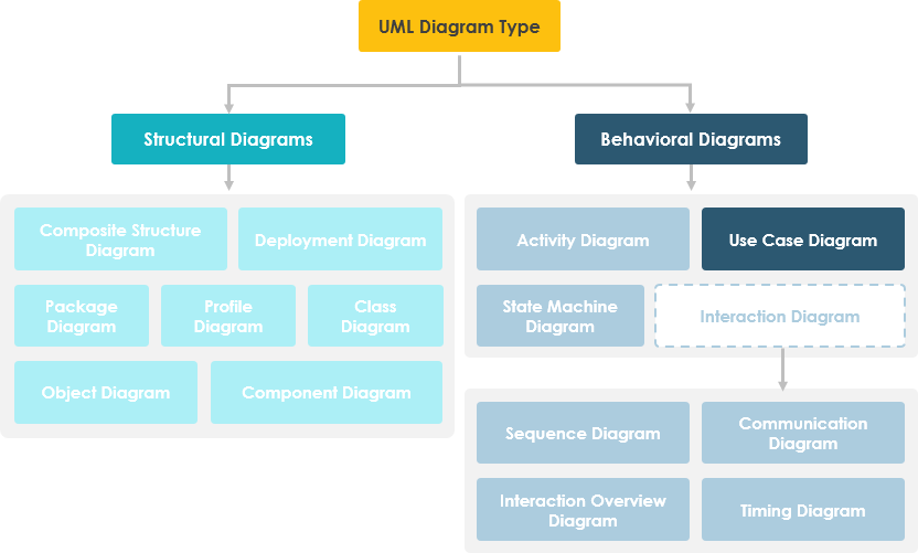
Use Case Diagrams belong to the behavioral diagram family within the broader UML ecosystem.
Origin and Evolution of Use Case Modeling
While Use Case Diagrams are now synonymous with UML, their conceptual roots predate the standardization of UML itself:
-
1986: Ivar Jacobson pioneered textual and visual techniques for specifying use cases, establishing the foundation for user-driven requirements modeling.
-
1992: Jacobson’s influential book, Object-Oriented Software Engineering – A Use Case Driven Approach, catalyzed widespread adoption of use cases in software engineering practice.
This historical context underscores a vital principle: Use Case modeling was designed from the outset to align technical development with business value—a principle that remains deeply relevant in agile, DevOps, and product-led development environments today.
Core Purpose and Strategic Value
Use Case Diagrams are typically developed during the inception and elaboration phases of a project. Their strategic purposes include:
| Purpose | Business Impact |
|---|---|
| Specify System Context | Clarifies system boundaries and external interactions |
| Capture Functional Requirements | Ensures stakeholder needs are explicitly documented |
| Validate System Architecture | Provides early feedback on design feasibility |
| Drive Implementation & Testing | Serves as traceable input for development and QA |
| Facilitate Cross-Functional Collaboration | Creates a shared language for analysts, developers, and domain experts |
By anchoring development efforts in user goals, Use Case Diagrams reduce ambiguity, minimize rework, and increase the likelihood of delivering software that users actually want and need.
Use Case Diagram Components at a Glance
A standard Use Case Diagram comprises four core elements, each with specific notation and semantics:
Actor

-
Represents a role played by a user or external system that interacts with the system
-
Named using nouns (e.g., Customer, Administrator, Payment Gateway)
-
A single user may play multiple actor roles depending on context
Use Case

-
Represents a system function or goal-oriented process
-
Named using verb+noun format (e.g., Place Order, Generate Report)
-
Each use case must deliver observable value to at least one actor
Communication Link

-
Solid line connecting an actor to a use case
-
Indicates participation: the actor triggers or interacts with the use case
System Boundary
-
Rectangle enclosing use cases to define system scope
-
For large systems, boundaries can represent modules (e.g., Payroll, Inventory)
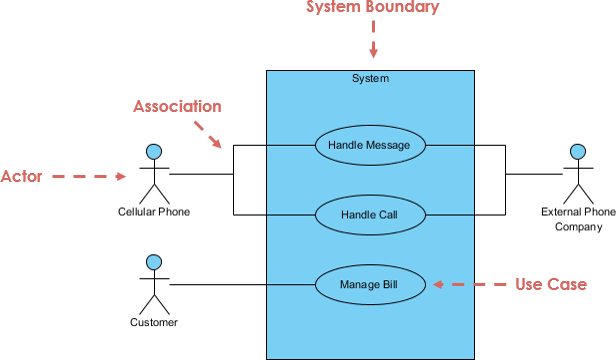
Annotated overview of standard Use Case Diagram notation
Structuring Use Cases: Relationships and Dependencies
Beyond basic elements, Use Case Diagrams leverage three relationship types to model complexity and promote reuse:
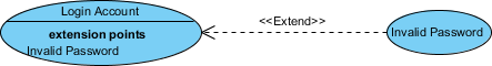
Extend Relationship
-
Models optional or conditional behavior
-
Syntax:
<<extend>>with dotted arrow pointing to base use case -
Example: Invalid Password extends Login Account
Include Relationship

-
Models mandatory reuse of common functionality
-
Syntax:
<<include>>with dotted arrow pointing to included use case -
Example: Place Order includes Validate Payment
Generalization Relationship

-
Models inheritance between use cases
-
Child use case specializes or overrides parent behavior
-
Shown with solid line and hollow triangle arrowhead
These relationships enable analysts to decompose complex requirements into manageable, reusable components while maintaining clear traceability.
AI-Powered Revolution in Requirements Elicitation
Modern tools are transforming Use Case modeling from a manual, time-intensive activity into an intelligent, collaborative workflow. Visual Paradigm’s AI ecosystem exemplifies this evolution:
Multi-Platform AI Support
-
VP Desktop: Generate Use Case Diagrams via AI and link them to detailed design artifacts
-
AI Chatbot: Draft and refine use case models through conversational interfaces
-
OpenDocs: Embed live, interactive Use Case Diagram pages directly into project documentation
Specialized Use Case AI Applications
-
🛠️ Use Case Modeling Studio: End-to-end AI workspace from scope definition to full Software Design Documents
-
📝 Description Generator: Instantly transform problem domains into specifications and PlantUML diagrams
-
⚡ Refinement Tool: Automatically apply UML best practices and
<<include>>/<<extend>>relationships -
🔄 Use Case to Activity: Bridge textual elaboration to visual behavioral modeling
-
📋 Report Generator: Convert visual diagrams into structured Markdown documentation
Explore the next generation of Use Case modeling:
AI Use Case Guide | Full AI Ecosystem
Practical Use Case Examples
Association Link Example
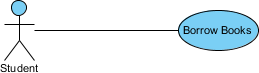
Basic actor-use case associations demonstrating system interactions
Include Relationship Example
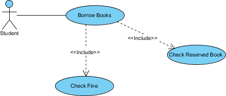
Demonstrates reuse of common behavior (e.g., authentication) across multiple use cases
Extend Relationship Example
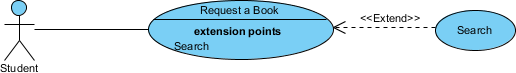
Shows optional behavior (e.g., advanced search) triggered under specific conditions
Generalization Relationship Example
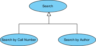
Illustrates inheritance: specialized use cases extending base functionality
Case Study: Vehicle Sales System Implementation
To demonstrate practical application, consider a Vehicle Sales System. Despite its business complexity, a well-structured Use Case Diagram captures core functionality with remarkable clarity:
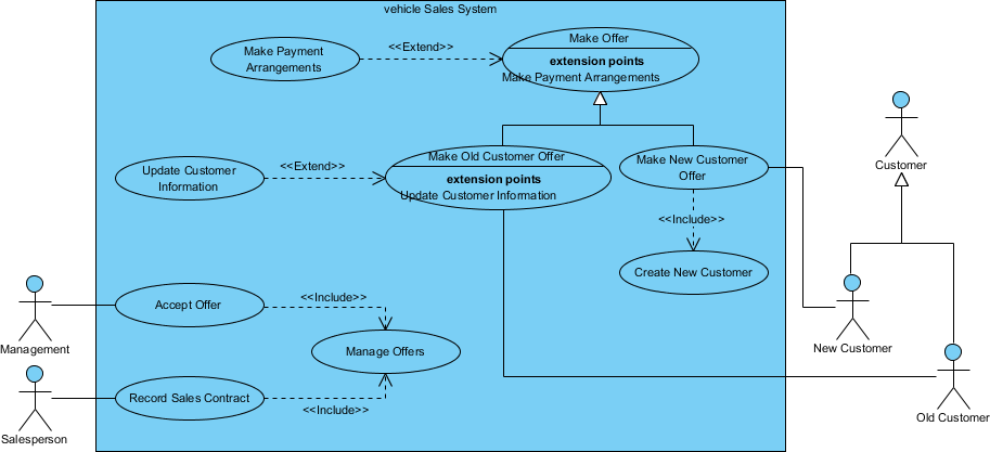
Key Observations:
-
Only 10 use cases model the entire system scope
-
Actors (Customer, Sales Agent, Inventory System) are clearly delineated
-
<<include>>relationships reuse common validation logic -
<<extend>>relationships handle exceptional flows (e.g., financing approval) -
System boundary cleanly separates internal processes from external interactions
This example proves that even enterprise-scale systems benefit from the disciplined simplicity of Use Case modeling.
Methodology: Identifying Actors and Use Cases
How to Identify Actors
Start requirements elicitation by asking:
-
Who uses, installs, maintains, or shuts down the system?
-
What external systems interact with this system?
-
Who provides input to or receives output from the system?
-
Are there time-based triggers requiring automated actors?
How to Identify Use Cases
Once actors are defined, ask:
-
What functions does each actor need from the system?
-
What information does the system store, and who manipulates it?
-
Does the system need to notify actors of state changes?
-
What external events must the system respond to?
This question-driven approach ensures comprehensive coverage of functional requirements while maintaining user-centric focus.
Best Practices and Tips for Effective Use Case Modeling
Apply these proven techniques to maximize the value of your Use Case Diagrams:
✅ Start from the Actor’s Perspective: Structure diagrams around user roles, not system modules
✅ Begin High-Level, Then Refine: Capture broad goals first; add detail only when necessary
✅ Focus on “What,” Not “How”: Describe desired outcomes, not implementation mechanics
✅ Limit Diagram Complexity: Keep diagrams under 20 use cases; use sub-diagrams for detail
✅ Link to Supporting Artifacts: Reference textual specifications, activity diagrams, or class diagrams for elaboration
💡 Pro Tip: Use Case Diagrams are communication tools first, documentation second. Prioritize clarity for stakeholders over technical completeness.
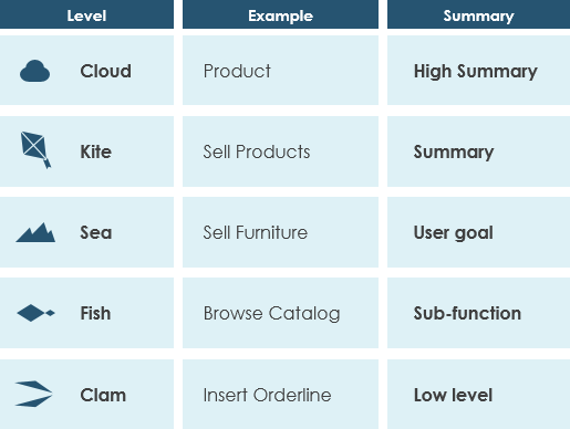
Granularity and Levels of Detail in Use Cases
Use case granularity—the level of detail in specifications—significantly impacts project communication and planning. Alastair Cockburn’s “sea level” metaphor provides an intuitive framework:
| Sea Level | Goal Scope | Typical Use |
|---|---|---|
| Cloud | Enterprise strategy | Portfolio planning |
| Kite | System-wide goals | Release planning |
| Sea | User goals (ideal level) | Sprint planning, use case diagrams |
| Fish | Sub-function steps | Detailed design, activity diagrams |
| Clam | Technical operations | Code-level specifications |
Recommendation: Draft Use Case Diagrams at the “Sea” level (user goals). Drill down to “Fish” or “Clam” levels only in supporting textual specifications or behavioral diagrams.
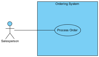
Advanced Tutorial: Linking Classes to Use Case Flow of Events
As projects evolve, data structures referenced in use case flows may change. Manually updating these references is error-prone and time-consuming. This tutorial demonstrates how to create synchronized links between class diagrams and use case flow of events using Visual Paradigm.
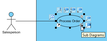
Step 1: Create a Class Diagram from a Use Case
-
Select the Process Order use case and click Sub Diagrams
-
Choose Add > Other Diagrams > UML Diagrams > Class Diagram
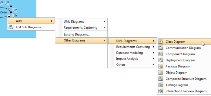
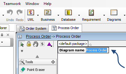
-
The new diagram inherits the use case name (Process Order)
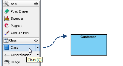
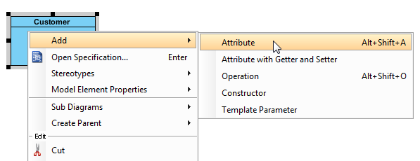
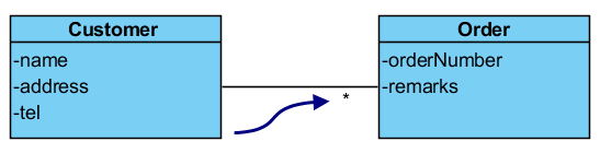
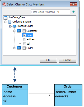
Step 2: Model Data Structures
-
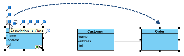
Add a Customer class with attributes: name, address, tel
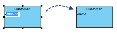
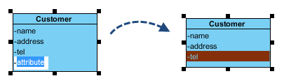
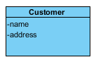
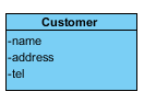
-
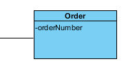
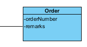
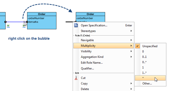
Add an Order class linked via association with multiplicity (*)
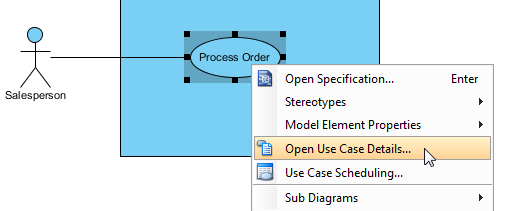
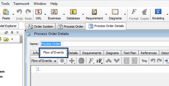
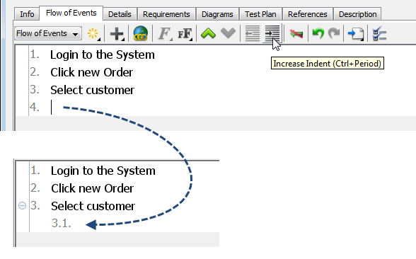
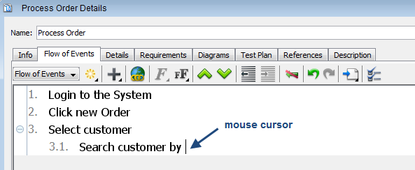
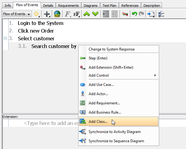
Step 3: Create Synchronized Flow of Events
-
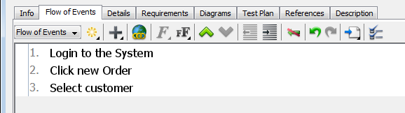
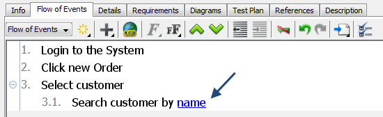
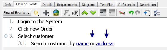
Open Process Order details and navigate to Flow of Events
-
Enter steps and insert class attributes via right-click > Add Class…
Step 4: Experience Automatic Synchronization
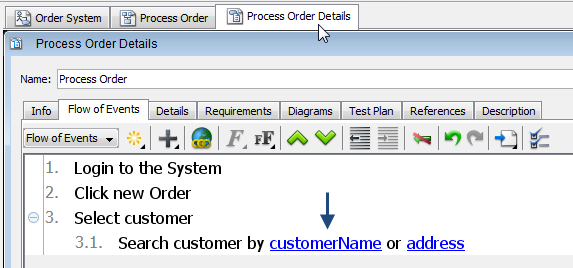
-
Rename attribute name to customerName in the class diagram
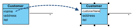
-
Return to Flow of Events: the change is reflected automatically
This synchronization capability eliminates manual maintenance overhead and ensures requirements documentation remains accurate as the system evolves.
Conclusion
Use Case Diagrams are far more than academic UML artifacts—they are strategic instruments for aligning business vision with technical execution. By modeling system behavior from the user’s perspective, they foster shared understanding, reduce ambiguity, and create a traceable foundation for development, testing, and validation.
This case study has demonstrated that effective Use Case modeling requires:
-
Discipline: Keeping diagrams simple, focused, and user-centric
-
Structure: Leveraging relationships (
<<include>>,<<extend>>, generalization) to manage complexity -
Tooling: Utilizing modern AI-enhanced platforms to accelerate elicitation and maintain synchronization
-
Granularity Awareness: Matching detail level to audience and purpose
As software systems grow increasingly complex and stakeholder expectations rise, the ability to clearly articulate what a system should do—before debating how to build it—becomes a decisive competitive advantage. Mastering Use Case Diagrams isn’t just about learning UML notation; it’s about cultivating a user-first mindset that delivers software people truly value.
Whether you’re initiating a greenfield project, modernizing a legacy system, or refining an existing product, invest time in crafting thoughtful Use Case Diagrams. Your future self—and your users—will thank you.
Reference List
- Unified Modeling Language: Wikipedia’s comprehensive overview of UML standards, diagram types, and modeling principles.
- Ivar Jacobson: Biographical resource on the pioneer of use case modeling and object-oriented software engineering.
- Visual Paradigm AI Chatbot: Conversational AI interface for drafting and refining use case models.
- OpenDocs by Visual Paradigm: Tool for creating and embedding live Use Case Diagram pages in project documentation.
- Use Case Modeling Studio: AI-powered end-to-end workspace for use case development and software design documentation.
- Use Case Description Generator: AI tool that transforms problem domains into specifications and PlantUML diagrams.
- Use Case Diagram Refinement Tool: Automated application of UML best practices and relationship modeling.
- Use Case to Activity Diagram Generator: AI bridge between textual use cases and visual behavioral modeling.
- Use Case Diagram Report Generator: Converts visual diagrams into structured Markdown documentation.
- AI Use Case Guide: Tutorial series on leveraging AI for use case modeling.
- Full AI Ecosystem Guide: Overview of Visual Paradigm’s integrated AI-powered diagramming tools.
- Overview of the 14 UML Diagram Types: Comprehensive guide to UML diagram families and their applications.
- UML Tool: Use Case Diagram Feature: Product page detailing Visual Paradigm’s use case modeling capabilities.
- Visual Paradigm Official Website: Homepage for the leading visual modeling and requirements management platform.
- Visual Paradigm Free Evaluation Download: Access to a 30-day free trial of Visual Paradigm with no registration required.
- YouTube: How to Define a Custom Property for Use Case: Video tutorial on extending use case metadata.
- YouTube: How to Generate Class Diagram from Existing Classes: Tutorial on reverse-engineering class diagrams from code.
- Organize Data Models Under Use Cases: Best practices for structuring data models within use case contexts.
- Full Set of UML Tools and Diagrams: Complete catalog of UML modeling features in Visual Paradigm.
