


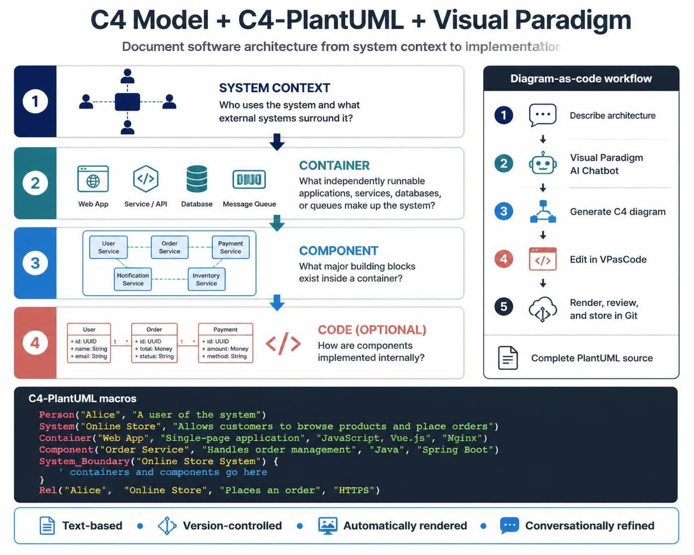
The C4 model is a practical way to document software architecture at progressively lower levels of detail:
-
System Context — Who uses the system and what external systems surround it?
-
Container — What independently runnable applications, services, databases, or queues make up the system?
-
Component — What major building blocks exist inside a container?
-
Code — How are components implemented internally? This level is optional and is usually represented with UML class or code-level diagrams.
C4-PlantUML combines the C4 model with PlantUML macros, allowing architecture diagrams to be stored as text, reviewed in Git, rendered automatically, and edited in Visual Paradigm VPasCode. The library provides macros such as Person, System, Container, Component, System_Boundary, and Rel.
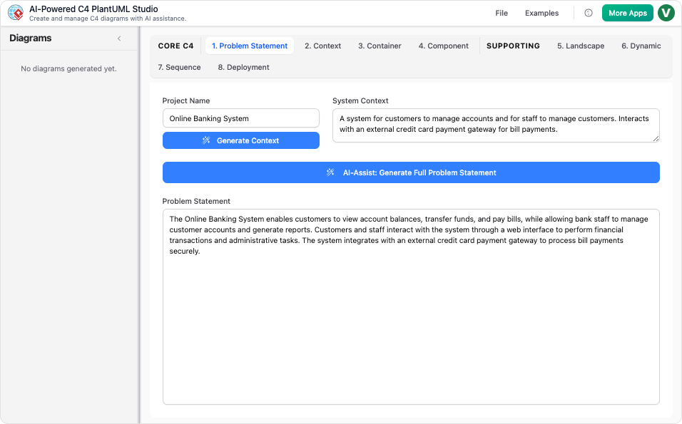
Visual Paradigm’s AI Chatbot supports C4 System Context, Container, Component, and Deployment diagrams. Generated diagrams can be refined conversationally and transferred to VPasCode for line-by-line editing.
1. Why use the C4 model?
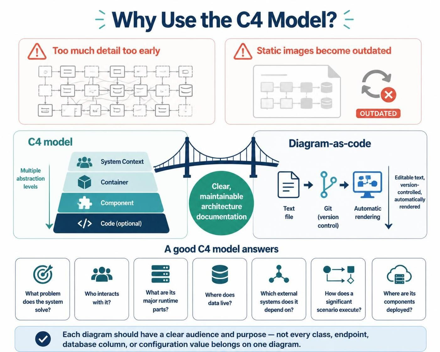
Architecture diagrams often fail for one of two reasons:
-
They show too much detail too early.
-
They are static images that become outdated.
C4 addresses the first problem by using multiple abstraction levels. Diagram-as-code addresses the second by storing the architecture in editable text.
A good C4 model should help a reader answer:
-
What problem does the system solve?
-
Who interacts with it?
-
What are its major runtime parts?
-
Where does data live?
-
Which external systems does it depend on?
-
How does a significant scenario execute?
-
Where are the system’s components deployed?
C4 diagrams are not intended to show every class, endpoint, database column, or configuration value. Each diagram should have a clear audience and purpose.
2. Example system: Online Food Ordering Platform
This guide uses an online food-ordering platform named QuickBite.
The platform allows customers to:
-
Browse restaurants and menus
-
Place food orders
-
Pay online
-
Track deliveries
-
Receive order notifications
The system integrates with:
-
Restaurant staff
-
Delivery drivers
-
A payment provider
-
A mapping provider
-
An email/SMS notification provider
The example architecture contains:
-
A web application
-
A mobile application
-
An API application
-
An order database
-
A payment integration
-
A delivery-tracking service
-
A message broker
-
A notification service
3. C4 concepts
3.1 Person
A person is a human user or role interacting with the system.
Examples:
-
Customer
-
Restaurant Manager
-
Delivery Driver
-
Support Agent
C4-PlantUML macros:
Person(customer, "Customer", "Places and tracks food orders")
Person_Ext(driver, "Delivery Driver", "Accepts and delivers orders")
Use Person_Ext when the person is outside the system boundary being documented.
3.2 Software system
A software system is the system being documented or an external system that it interacts with.
Examples:
-
QuickBite Platform
-
Payment Provider
-
Mapping Provider
C4-PlantUML macros:
System(quickbite, "QuickBite Platform", "Online food ordering platform")
System_Ext(payment, "Payment Provider", "Processes card and wallet payments")
3.3 Container
A container is an independently runnable or deployable unit. It is not necessarily a Docker container.
Examples:
-
Web application
-
REST API
-
Database
-
Message broker
-
Background worker
C4-PlantUML macros:
Container(web, "Web Application", "React", "Allows customers to browse restaurants and place orders")
ContainerDb(database, "Order Database", "PostgreSQL", "Stores customers, menus, orders, and payments")
3.4 Component
A component is a cohesive group of related functionality inside a container.
Examples inside an API:
-
Restaurant Catalog Controller
-
Order Service
-
Payment Service
-
Delivery Service
-
Authentication Service
C4-PlantUML macros:
Component(orderService, "Order Service", "Application service", "Creates and manages customer orders")
Component(paymentService, "Payment Service", "Application service", "Authorizes and records payments")
3.5 Relationship
A relationship explains how two elements interact.
A useful relationship normally states:
-
What action takes place
-
Which protocol or technology is used
-
Sometimes the data being exchanged
Examples:
Rel(customer, web, "Browses and places orders", "HTTPS")
Rel(api, database, "Reads and writes order data", "SQL")
Rel(paymentService, payment, "Authorizes payments", "HTTPS/JSON")
Avoid vague labels such as “uses” when you can provide a more meaningful description.
4. The Visual Paradigm workflow
A productive workflow combines conversational generation with controlled source-code editing:
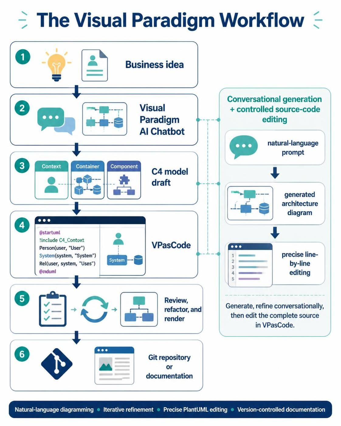
Visual Paradigm describes the AI Chatbot as a natural-language diagramming interface that can generate architecture diagrams and support iterative refinement. The generated code can be opened in VPasCode for precise editing.
4.1 Start with a structured prompt
Instead of asking:
Create a system architecture diagram.
use a prompt containing:
-
System name
-
Users
-
External systems
-
Main responsibilities
-
Technology constraints
-
Desired C4 level
-
Required output format
-
Relationship protocols
Example AI Chatbot prompt:
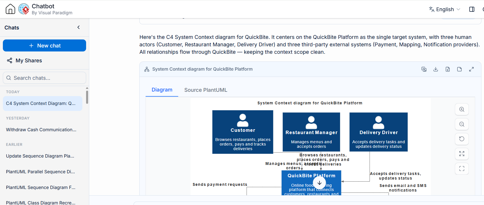
Create a C4 System Context diagram for QuickBite, an online food-ordering platform.

Include:
- Customer
- Restaurant Manager
- Delivery Driver
- Payment Provider
- Mapping Provider
- Notification Provider
- QuickBite Platform

Show these relationships:
- Customers browse restaurants, place orders, pay, and track deliveries.
- Restaurant Managers manage menus and accept orders.
- Delivery Drivers accept delivery tasks and update delivery status.
- QuickBite sends payment requests to the Payment Provider.
- QuickBite retrieves route and location information from the Mapping Provider.
- QuickBite sends email and SMS notifications through the Notification Provider.

Generate complete C4-PlantUML source code, including @startuml, the C4 include, all elements, relationships, and @enduml.
Send to VPasCode Editor for Preview and Editing
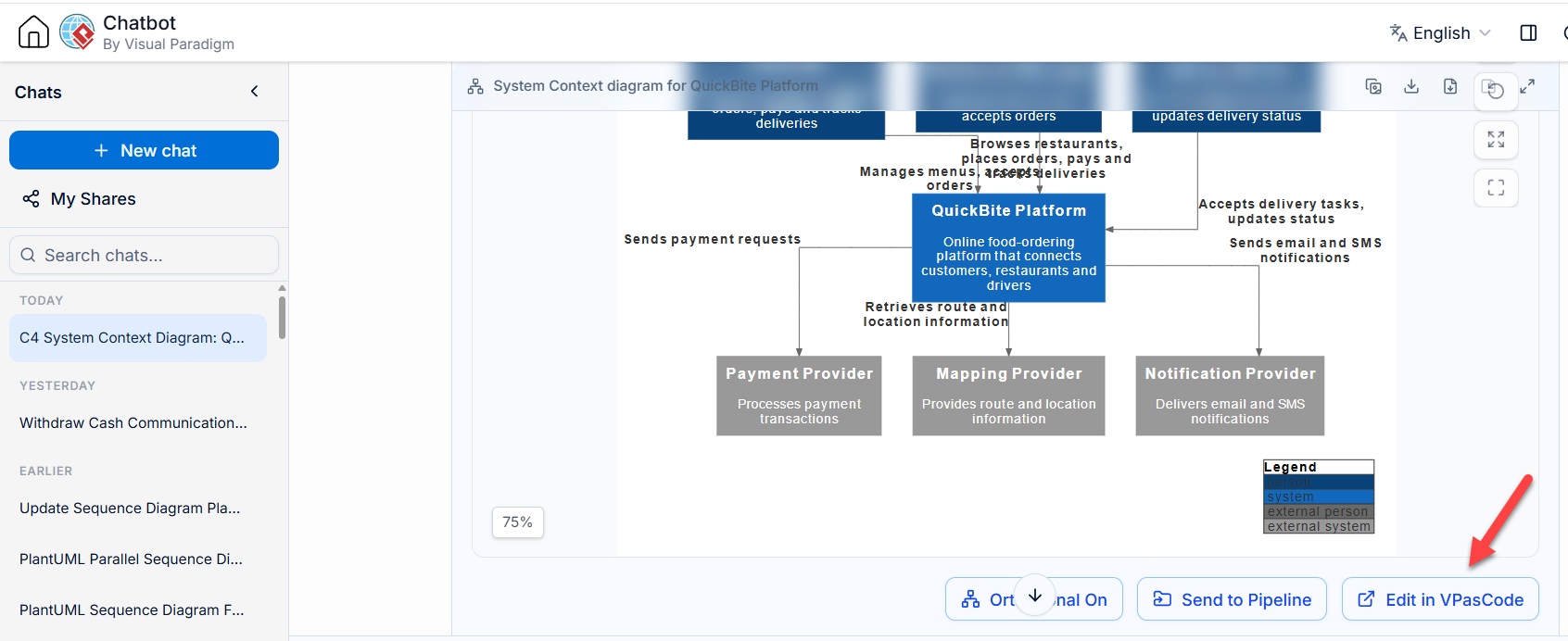
4.2 Refine conversationally
Useful follow-up prompts include:
Move the Payment Provider outside the QuickBite system boundary.
Add HTTPS to all external integrations and REST/JSON to application relationships.
Remove implementation details from the System Context diagram.
Generate the corresponding Container diagram for the QuickBite Platform.
Check whether every relationship has a source, target, action, and protocol.
The AI-generated output should be treated as a draft. Validate names, boundaries, responsibilities, and relationships against the actual system.
4.3 Open the result in VPasCode
Use VPasCode to:
-
Inspect the complete PlantUML source
-
Correct aliases and relationships
-
Add or remove containers
-
Refine layout directives
-
Apply consistent styles
-
Render the diagram
-
Export SVG or PNG
-
Store the source in version control
VPasCode is designed to render PlantUML and other diagram-as-code formats in real time, with AI-assisted error fixing and format detection.
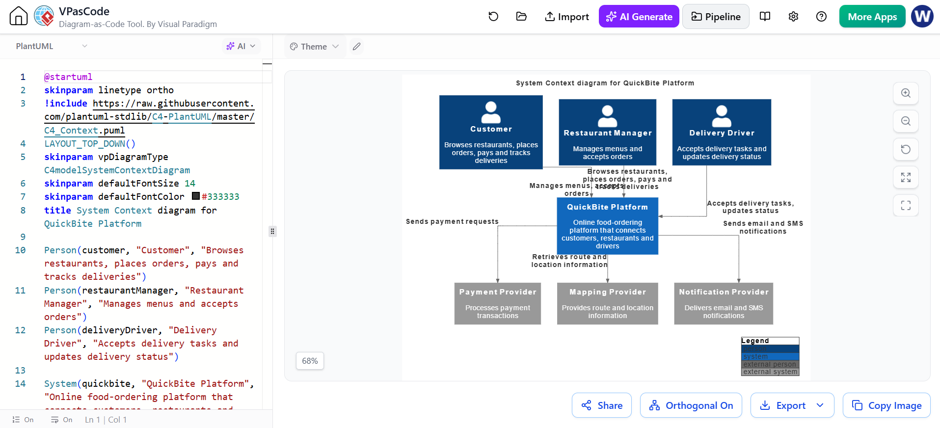
5. C4-PlantUML setup
5.1 Remote include
The simplest approach is to include the current library directly from GitHub:
!include https://raw.githubusercontent.com/plantuml-stdlib/C4-PlantUML/master/C4_Context.puml
This requires network access whenever the diagram is rendered.
5.2 Local include
For reproducible or offline builds, download the appropriate C4-PlantUML files and place them beside your .puml files.
The C4-PlantUML documentation supports local rendering with:
-DRELATIVE_INCLUDE=.
This avoids depending on an Internet connection during every render.
5.3 Standard-library include
When using a recent PlantUML distribution that contains the C4 standard library, you can use:
This avoids external includes and uses the integrated PlantUML standard library.
For the examples below, the remote GitHub include is used because it clearly identifies the requested C4-PlantUML source.
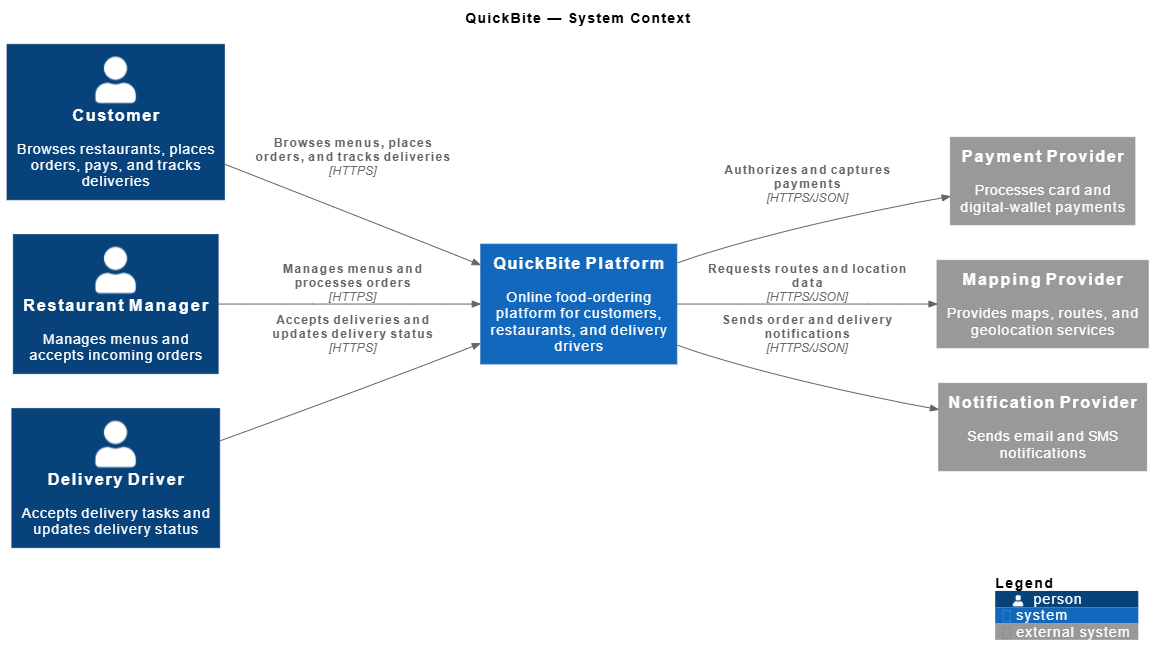
6. Level 1: System Context Diagram
A System Context diagram shows the system as a single box in its environment.
It should normally include:
-
Human users
-
External systems
-
The system being documented
-
High-level relationships
It should not normally include:
-
Internal services
-
Databases
-
Frameworks
-
Programming languages
-
Internal implementation details
Complete C4-PlantUML example
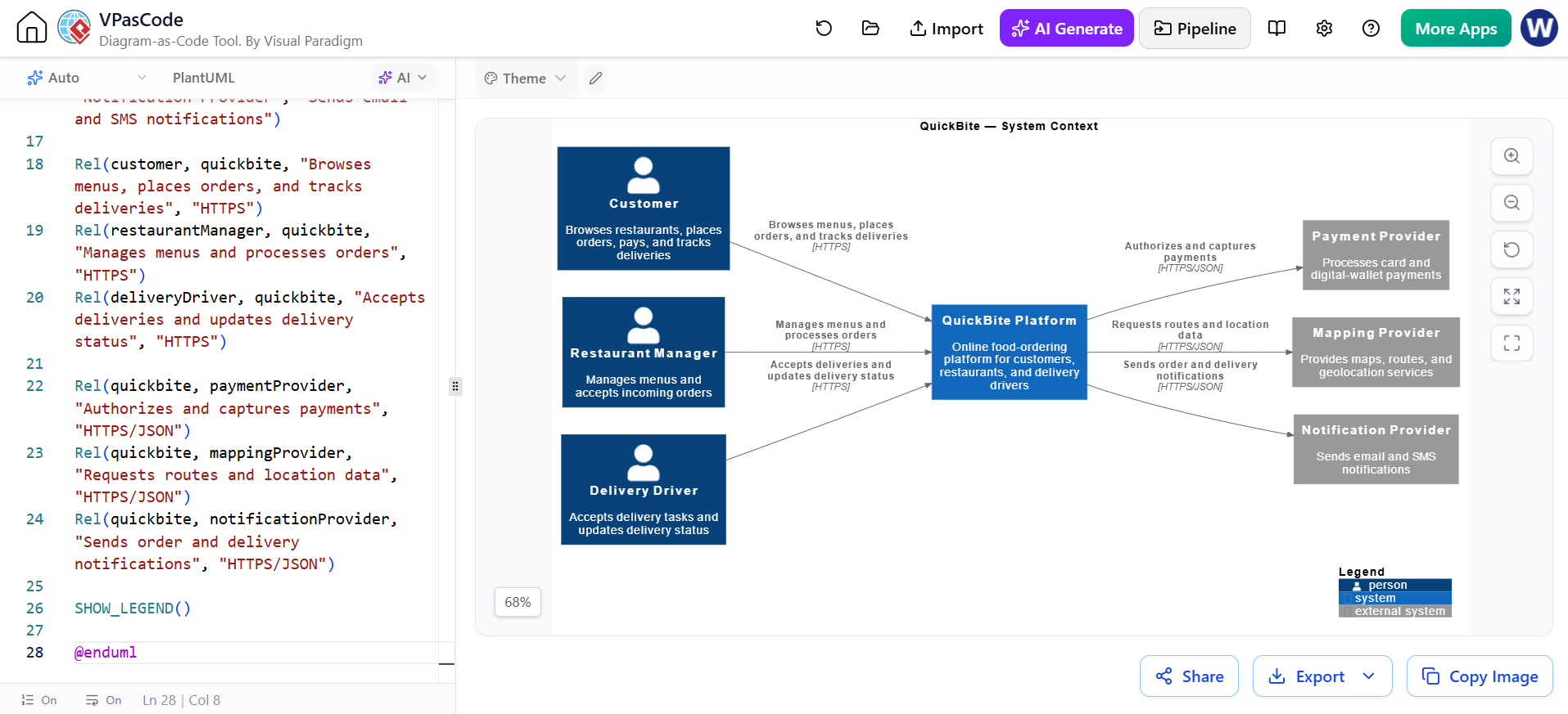
@startuml QuickBite-System-Context

!include https://raw.githubusercontent.com/plantuml-stdlib/C4-PlantUML/master/C4_Context.puml

LAYOUT_LEFT_RIGHT()
title QuickBite — System Context

Person(customer, "Customer", "Browses restaurants, places orders, pays, and tracks deliveries")
Person(restaurantManager, "Restaurant Manager", "Manages menus and accepts incoming orders")
Person(deliveryDriver, "Delivery Driver", "Accepts delivery tasks and updates delivery status")

System(quickbite, "QuickBite Platform", "Online food-ordering platform for customers, restaurants, and delivery drivers")

System_Ext(paymentProvider, "Payment Provider", "Processes card and digital-wallet payments")
System_Ext(mappingProvider, "Mapping Provider", "Provides maps, routes, and geolocation services")
System_Ext(notificationProvider, "Notification Provider", "Sends email and SMS notifications")

Rel(customer, quickbite, "Browses menus, places orders, and tracks deliveries", "HTTPS")
Rel(restaurantManager, quickbite, "Manages menus and processes orders", "HTTPS")
Rel(deliveryDriver, quickbite, "Accepts deliveries and updates delivery status", "HTTPS")

Rel(quickbite, paymentProvider, "Authorizes and captures payments", "HTTPS/JSON")
Rel(quickbite, mappingProvider, "Requests routes and location data", "HTTPS/JSON")
Rel(quickbite, notificationProvider, "Sends order and delivery notifications", "HTTPS/JSON")

SHOW_LEGEND()

@enduml
What this diagram communicates
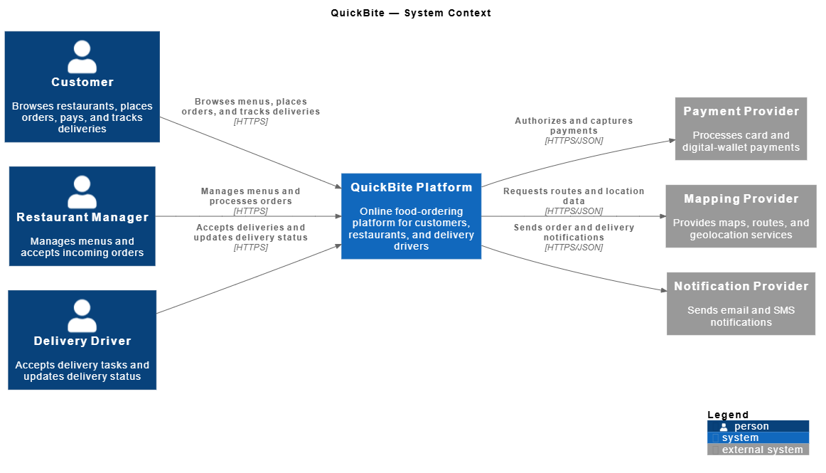
The diagram establishes:
-
QuickBite’s scope
-
Its human users
-
Its external dependencies
-
The main business interactions
It intentionally hides the web application, API, database, and message broker. Those belong in the Container diagram.
AI Chatbot prompt for this level
Review this System Context diagram for C4 quality.

Check:
1. Is QuickBite represented as one system?
2. Are implementation details excluded?
3. Are all external systems outside the QuickBite boundary?
4. Does every relationship describe a meaningful business interaction?
5. Are protocols included only where they are useful?

Return recommendations and then provide a corrected complete PlantUML file.
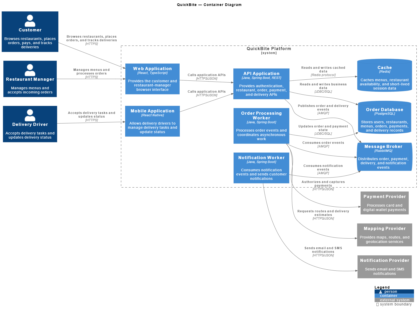
7. Level 2: Container Diagram
A Container diagram expands one software system into its major deployable or independently runnable parts.
Typical elements include:
-
Web applications
-
Mobile applications
-
APIs
-
Databases
-
Message brokers
-
Background workers
-
External systems
The goal is to explain the system’s overall technology shape without exposing classes or method-level details.
Complete C4-PlantUML example
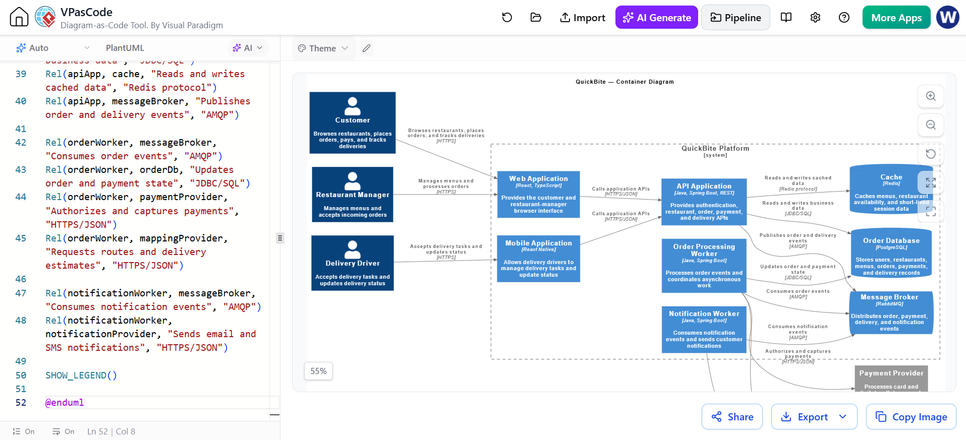
@startuml QuickBite-Containers

!include https://raw.githubusercontent.com/plantuml-stdlib/C4-PlantUML/master/C4_Container.puml

LAYOUT_LEFT_RIGHT()
title QuickBite — Container Diagram

Person(customer, "Customer", "Browses restaurants, places orders, pays, and tracks deliveries")
Person(restaurantManager, "Restaurant Manager", "Manages menus and accepts incoming orders")
Person(deliveryDriver, "Delivery Driver", "Accepts delivery tasks and updates delivery status")

System_Ext(paymentProvider, "Payment Provider", "Processes card and digital-wallet payments")
System_Ext(mappingProvider, "Mapping Provider", "Provides maps, routes, and geolocation services")
System_Ext(notificationProvider, "Notification Provider", "Sends email and SMS notifications")

System_Boundary(quickbite, "QuickBite Platform") {
    Container(webApp, "Web Application", "React, TypeScript", "Provides the customer and restaurant-manager browser interface")
    Container(mobileApp, "Mobile Application", "React Native", "Allows delivery drivers to manage delivery tasks and update status")

    Container(apiApp, "API Application", "Java, Spring Boot, REST", "Provides authentication, restaurant, order, payment, and delivery APIs")

    Container(orderWorker, "Order Processing Worker", "Java, Spring Boot", "Processes order events and coordinates asynchronous work")
    Container(notificationWorker, "Notification Worker", "Java, Spring Boot", "Consumes notification events and sends customer notifications")

    ContainerDb(orderDb, "Order Database", "PostgreSQL", "Stores users, restaurants, menus, orders, payments, and delivery records")
    ContainerDb(cache, "Cache", "Redis", "Caches menus, restaurant availability, and short-lived session data")

    ContainerQueue(messageBroker, "Message Broker", "RabbitMQ", "Distributes order, payment, delivery, and notification events")
}

Rel(customer, webApp, "Browses restaurants, places orders, and tracks deliveries", "HTTPS")
Rel(restaurantManager, webApp, "Manages menus and processes orders", "HTTPS")
Rel(deliveryDriver, mobileApp, "Accepts delivery tasks and updates status", "HTTPS")

Rel(webApp, apiApp, "Calls application APIs", "HTTPS/JSON")
Rel(mobileApp, apiApp, "Calls application APIs", "HTTPS/JSON")

Rel(apiApp, orderDb, "Reads and writes business data", "JDBC/SQL")
Rel(apiApp, cache, "Reads and writes cached data", "Redis protocol")
Rel(apiApp, messageBroker, "Publishes order and delivery events", "AMQP")

Rel(orderWorker, messageBroker, "Consumes order events", "AMQP")
Rel(orderWorker, orderDb, "Updates order and payment state", "JDBC/SQL")
Rel(orderWorker, paymentProvider, "Authorizes and captures payments", "HTTPS/JSON")
Rel(orderWorker, mappingProvider, "Requests routes and delivery estimates", "HTTPS/JSON")

Rel(notificationWorker, messageBroker, "Consumes notification events", "AMQP")
Rel(notificationWorker, notificationProvider, "Sends email and SMS notifications", "HTTPS/JSON")

SHOW_LEGEND()

@enduml
Container modeling rules
A container should have a meaningful responsibility.
Good:
Order Processing Worker
Notification Worker
Order Database
Less useful:
Java Module
Utility Package
Common Code
A container is usually something that can be:
-
Run independently
-
Deployed independently
-
Scaled independently
-
Owned by a team
-
Replaced by another implementation
A database is commonly represented with ContainerDb. A queue or message broker can be represented with ContainerQueue.
AI Chatbot prompt for this level
Generate a complete C4-PlantUML Container diagram for QuickBite.

Use this system context:
- Customers use QuickBite to browse, order, pay, and track deliveries.
- Restaurant Managers manage menus and orders.
- Delivery Drivers use a mobile application.
- QuickBite integrates with payment, mapping, and notification providers.

Use these containers:
- React web application
- React Native mobile application
- Java Spring Boot REST API
- Order Processing Worker
- Notification Worker
- PostgreSQL Order Database
- Redis Cache
- RabbitMQ Message Broker

Show:
- Human-to-application relationships
- Application-to-API relationships
- API-to-database and cache relationships
- Asynchronous worker relationships
- External payment, mapping, and notification integrations

Return only a complete PlantUML file with @startuml, the C4_Container include, all declarations, relationships, legend, and @enduml.
8. Level 3: Component Diagram
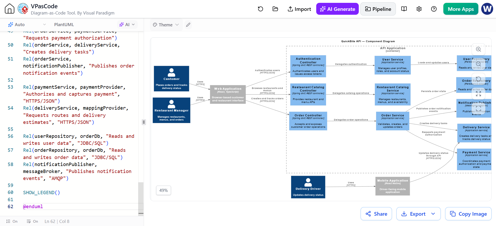
A Component diagram expands one container. It should focus on the internal structure of that container, not the entire system.
For QuickBite, the API application can be divided into:
-
Authentication Controller
-
Restaurant Catalog Controller
-
Order Controller
-
Order Service
-
Payment Service
-
Delivery Service
-
Notification Publisher
-
User Repository
-
Order Repository
Components should be cohesive and communicate through clear responsibilities.
Complete C4-PlantUML example
@startuml QuickBite-API-Components

!include https://raw.githubusercontent.com/plantuml-stdlib/C4-PlantUML/master/C4_Component.puml

LAYOUT_LEFT_RIGHT()
title QuickBite API — Component Diagram

Person(customer, "Customer", "Places orders and tracks delivery status")
Person(restaurantManager, "Restaurant Manager", "Manages restaurants, menus, and orders")
Person(deliveryDriver, "Delivery Driver", "Updates delivery status")

Container_Ext(webApp, "Web Application", "React, TypeScript", "Browser-based customer and restaurant interface")
Container_Ext(mobileApp, "Mobile Application", "React Native", "Driver-facing mobile application")

Container_Boundary(apiApp, "API Application") {
    Component(authController, "Authentication Controller", "Spring MVC REST controller", "Authenticates users and issues access tokens")
    Component(userService, "User Service", "Application service", "Manages user profiles, roles, and account status")
    Component(restaurantController, "Restaurant Catalog Controller", "Spring MVC REST controller", "Provides restaurant and menu APIs")
    Component(restaurantService, "Restaurant Catalog Service", "Application service", "Manages restaurants, menus, and availability")
    Component(orderController, "Order Controller", "Spring MVC REST controller", "Accepts and exposes customer order operations")
    Component(orderService, "Order Service", "Application service", "Validates, creates, and updates orders")
    Component(paymentService, "Payment Service", "Application service", "Coordinates payment authorization and payment state")
    Component(deliveryService, "Delivery Service", "Application service", "Creates delivery tasks and tracks delivery status")
    Component(notificationPublisher, "Notification Publisher", "Messaging adapter", "Publishes notification events")
    Component(userRepository, "User Repository", "Persistence adapter", "Reads and writes user data")
    Component(orderRepository, "Order Repository", "Persistence adapter", "Reads and writes order data")
}

ContainerDb(orderDb, "Order Database", "PostgreSQL", "Stores users, restaurants, menus, orders, payments, and delivery records")
ContainerQueue(messageBroker, "Message Broker", "RabbitMQ", "Distributes asynchronous application events")
System_Ext(paymentProvider, "Payment Provider", "Processes card and wallet payments")
System_Ext(mappingProvider, "Mapping Provider", "Provides routes and geolocation services")

Rel(customer, webApp, "Uses", "HTTPS")
Rel(restaurantManager, webApp, "Uses", "HTTPS")
Rel(deliveryDriver, mobileApp, "Uses", "HTTPS")

Rel(webApp, authController, "Authenticates users", "HTTPS/JSON")
Rel(webApp, restaurantController, "Browses restaurants and menus", "HTTPS/JSON")
Rel(webApp, orderController, "Creates and tracks orders", "HTTPS/JSON")
Rel(mobileApp, deliveryService, "Updates delivery status through API", "HTTPS/JSON")

Rel(authController, userService, "Delegates authentication")
Rel(userService, userRepository, "Loads and updates users")
Rel(restaurantController, restaurantService, "Delegates catalog operations")
Rel(orderController, orderService, "Delegates order operations")

Rel(orderService, orderRepository, "Persists order state")
Rel(orderService, paymentService, "Requests payment authorization")
Rel(orderService, deliveryService, "Creates delivery tasks")
Rel(orderService, notificationPublisher, "Publishes order notification events")

Rel(paymentService, paymentProvider, "Authorizes and captures payment", "HTTPS/JSON")
Rel(deliveryService, mappingProvider, "Requests routes and delivery estimates", "HTTPS/JSON")

Rel(userRepository, orderDb, "Reads and writes user data", "JDBC/SQL")
Rel(orderRepository, orderDb, "Reads and writes order data", "JDBC/SQL")
Rel(notificationPublisher, messageBroker, "Publishes notification events", "AMQP")

SHOW_LEGEND()

@enduml
Component diagram guidance
A component diagram is useful when readers need to understand:
-
Ownership boundaries
-
Internal responsibilities
-
Dependency direction
-
Integration points
-
Testable units
-
Refactoring opportunities
Avoid creating one component for every class. A component should represent a meaningful architectural responsibility.
A useful test is:
Could I explain why this component changes independently from the others?
If the answer is no, the component may be too granular or incorrectly divided.
AI Chatbot prompt for this level
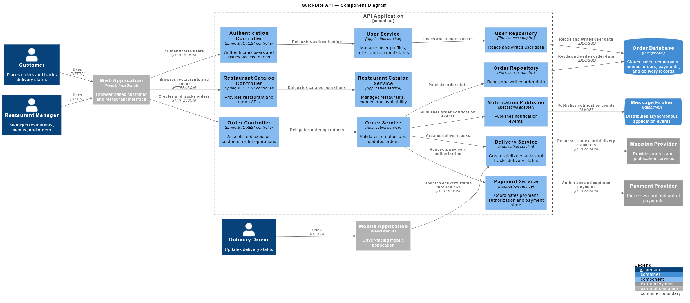
Create a complete C4-PlantUML Component diagram for the QuickBite API Application.

The API contains:
- Authentication Controller
- User Service
- Restaurant Catalog Controller
- Restaurant Catalog Service
- Order Controller
- Order Service
- Payment Service
- Delivery Service
- Notification Publisher
- User Repository
- Order Repository

Include external relationships from:
- Web Application
- Mobile Application
- PostgreSQL Order Database
- RabbitMQ Message Broker
- Payment Provider
- Mapping Provider

Show dependency direction and use meaningful relationship labels. Do not create a class diagram. Return complete executable PlantUML source code.
9. Level 4: Code diagrams
The C4 model treats code-level diagrams as optional. Use them when implementation structure is important, such as:
-
A complex domain model
-
A reusable library
-
A security subsystem
-
A difficult algorithm
-
A legacy component being redesigned
-
A critical persistence pattern
Do not generate code-level diagrams for every part of the application. They become difficult to maintain quickly.
A code diagram can be generated with ordinary PlantUML UML notation. It does not need to use the C4-PlantUML library.
Complete PlantUML example
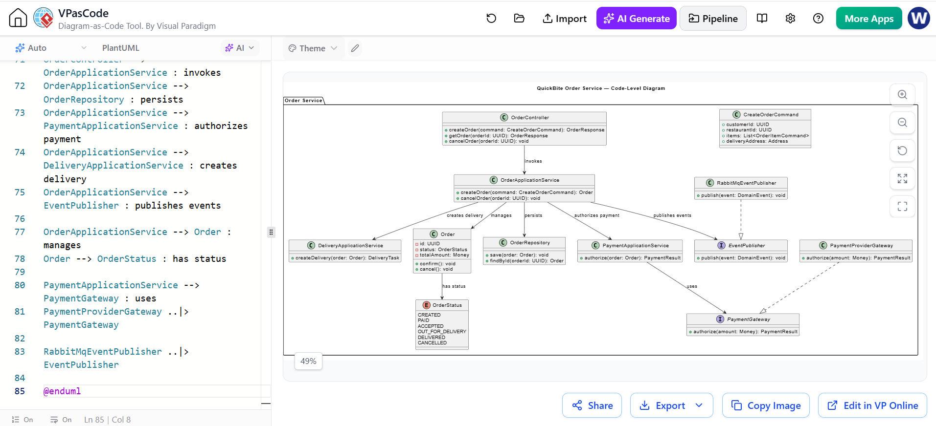
@startuml QuickBite-Order-Code

title QuickBite Order Service — Code-Level Diagram

package "Order Service" {
    class OrderController {
        +createOrder(command: CreateOrderCommand): OrderResponse
        +getOrder(orderId: UUID): OrderResponse
        +cancelOrder(orderId: UUID): void
    }

    class OrderApplicationService {
        +createOrder(command: CreateOrderCommand): Order
        +cancelOrder(orderId: UUID): void
    }

    class PaymentApplicationService {
        +authorize(order: Order): PaymentResult
    }

    class DeliveryApplicationService {
        +createDelivery(order: Order): DeliveryTask
    }

    class Order {
        -id: UUID
        -status: OrderStatus
        -totalAmount: Money
        +confirm(): void
        +cancel(): void
    }

    enum OrderStatus {
        CREATED
        PAID
        ACCEPTED
        OUT_FOR_DELIVERY
        DELIVERED
        CANCELLED
    }

    class CreateOrderCommand {
        +customerId: UUID
        +restaurantId: UUID
        +items: List<OrderItemCommand>
        +deliveryAddress: Address
    }

    class OrderRepository {
        +save(order: Order): void
        +findById(orderId: UUID): Order
    }

    interface PaymentGateway {
        +authorize(amount: Money): PaymentResult
    }

    class PaymentProviderGateway {
        +authorize(amount: Money): PaymentResult
    }

    interface EventPublisher {
        +publish(event: DomainEvent): void
    }

    class RabbitMqEventPublisher {
        +publish(event: DomainEvent): void
    }
}

OrderController --> OrderApplicationService : invokes
OrderApplicationService --> OrderRepository : persists
OrderApplicationService --> PaymentApplicationService : authorizes payment
OrderApplicationService --> DeliveryApplicationService : creates delivery
OrderApplicationService --> EventPublisher : publishes events

OrderApplicationService --> Order : manages
Order --> OrderStatus : has status

PaymentApplicationService --> PaymentGateway : uses
PaymentProviderGateway ..|> PaymentGateway

RabbitMqEventPublisher ..|> EventPublisher

@enduml
AI Chatbot prompt for a code-level diagram
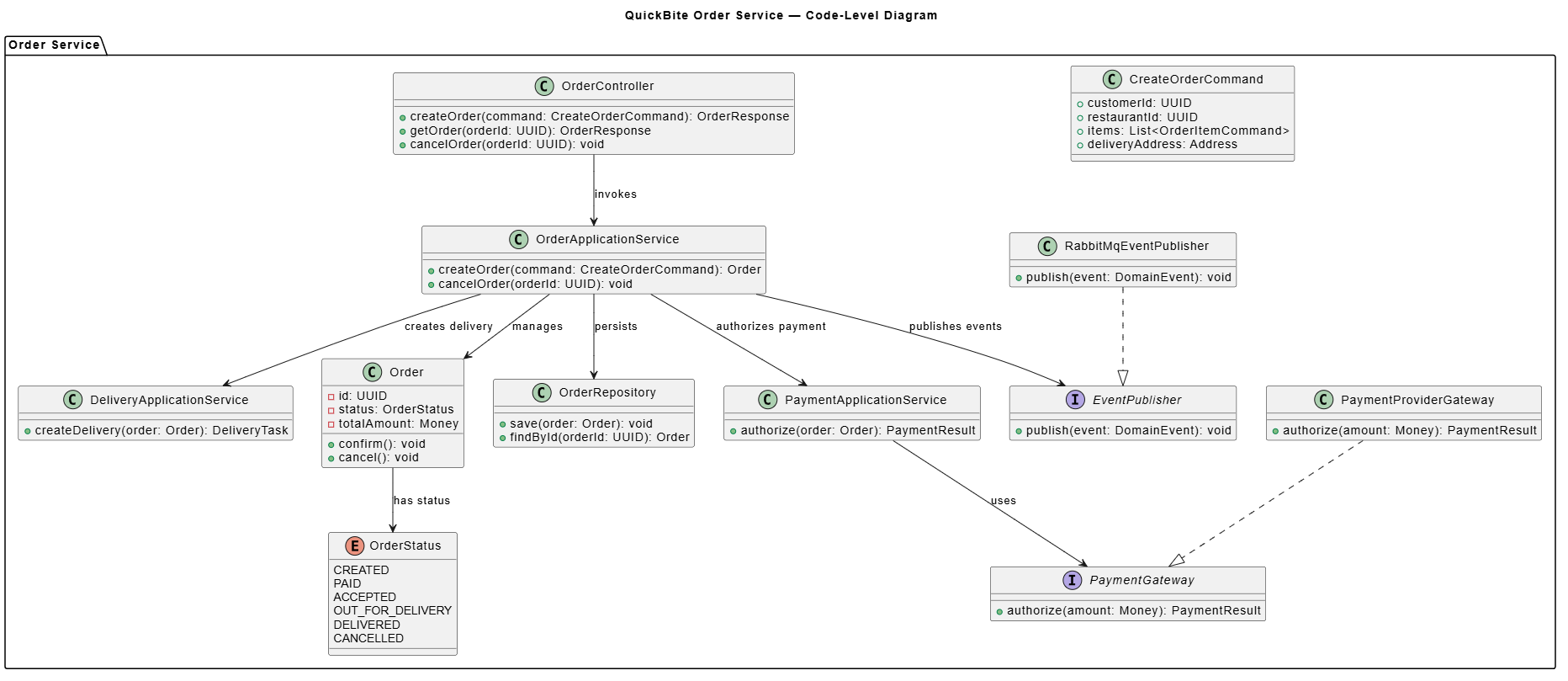
Generate a complete PlantUML class diagram for the QuickBite Order Service.

Include:
- OrderController
- OrderApplicationService
- PaymentApplicationService
- DeliveryApplicationService
- Order
- OrderStatus
- CreateOrderCommand
- OrderRepository
- PaymentGateway
- PaymentProviderGateway
- EventPublisher
- RabbitMqEventPublisher

Show interfaces, implementations, dependencies, and important public operations. Do not include unrelated classes. Return an executable PlantUML file.
10. Dynamic diagrams
Static C4 diagrams describe structure. Dynamic diagrams describe how elements collaborate during a particular scenario.
A dynamic diagram is useful for:
-
Checkout
-
User authentication
-
Payment authorization
-
Order fulfillment
-
Delivery tracking
-
Failure handling
The scenario should be specific. Avoid trying to represent the entire runtime behavior in one diagram.
Complete C4-PlantUML dynamic diagram
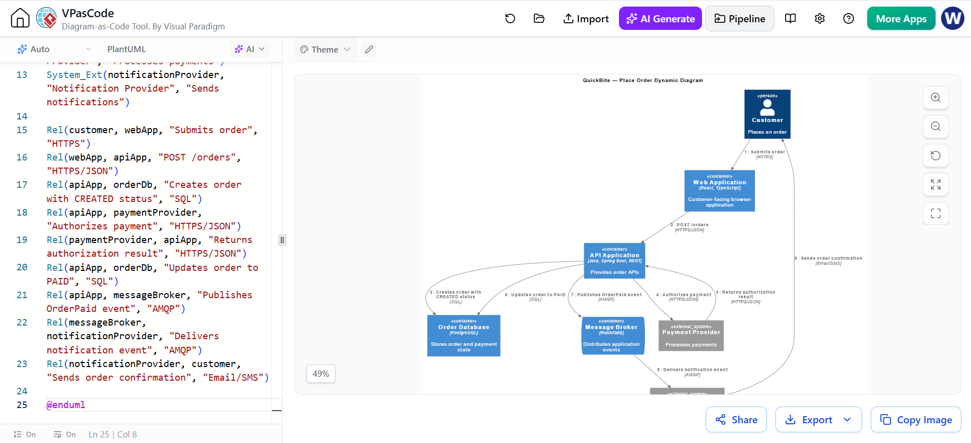
@startuml QuickBite-Order-Dynamic

!include https://raw.githubusercontent.com/plantuml-stdlib/C4-PlantUML/master/C4_Dynamic.puml

title QuickBite — Place Order Dynamic Diagram

Person(customer, "Customer", "Places an order")
Container(webApp, "Web Application", "React, TypeScript", "Customer-facing browser application")
Container(apiApp, "API Application", "Java, Spring Boot, REST", "Provides order APIs")
Container(orderDb, "Order Database", "PostgreSQL", "Stores order and payment state")
ContainerQueue(messageBroker, "Message Broker", "RabbitMQ", "Distributes application events")
System_Ext(paymentProvider, "Payment Provider", "Processes payments")
System_Ext(notificationProvider, "Notification Provider", "Sends notifications")

Rel(customer, webApp, "Submits order", "HTTPS")
Rel(webApp, apiApp, "POST /orders", "HTTPS/JSON")
Rel(apiApp, orderDb, "Creates order with CREATED status", "SQL")
Rel(apiApp, paymentProvider, "Authorizes payment", "HTTPS/JSON")
Rel(paymentProvider, apiApp, "Returns authorization result", "HTTPS/JSON")
Rel(apiApp, orderDb, "Updates order to PAID", "SQL")
Rel(apiApp, messageBroker, "Publishes OrderPaid event", "AMQP")
Rel(messageBroker, notificationProvider, "Delivers notification event", "AMQP")
Rel(notificationProvider, customer, "Sends order confirmation", "Email/SMS")

@enduml
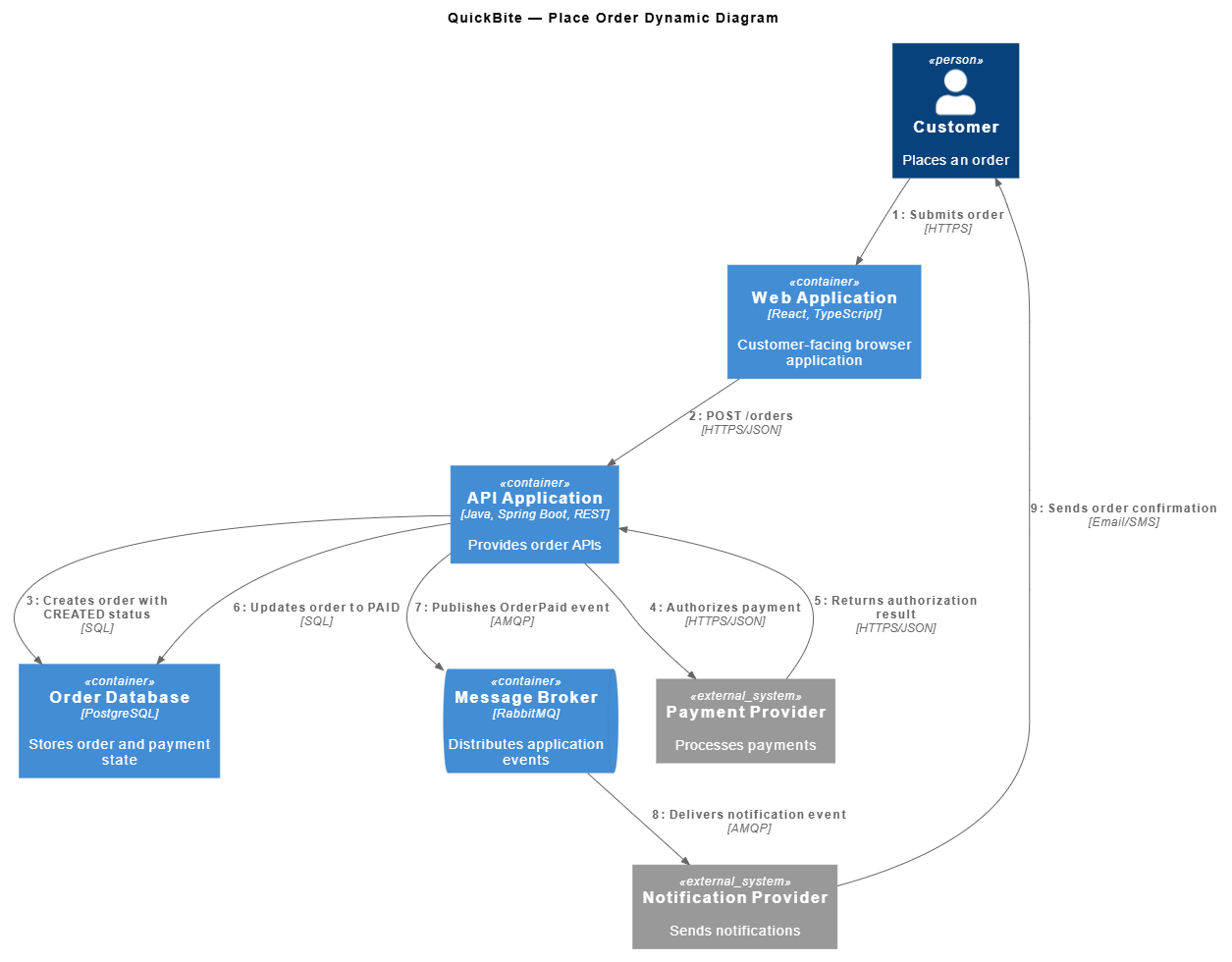
Dynamic diagram guidance
A dynamic diagram should normally have:
-
A scenario title
-
A clear starting actor
-
A small number of participants
-
Ordered interactions
-
Success and, where useful, failure paths
For complex branching behavior, use a regular PlantUML sequence diagram or activity diagram instead of forcing every behavior into a C4 dynamic diagram.
11. Deployment diagrams
A deployment diagram shows where containers run.
It can include:
-
Deployment nodes
-
Hosts
-
Cloud regions
-
Kubernetes clusters
-
Virtual machines
-
Databases
-
Container instances
-
Network zones
The deployment view answers:
-
Where is the software deployed?
-
Which nodes host which containers?
-
Which services are public?
-
Which components are in a private network?
-
Where are databases and queues located?
Complete C4-PlantUML deployment example
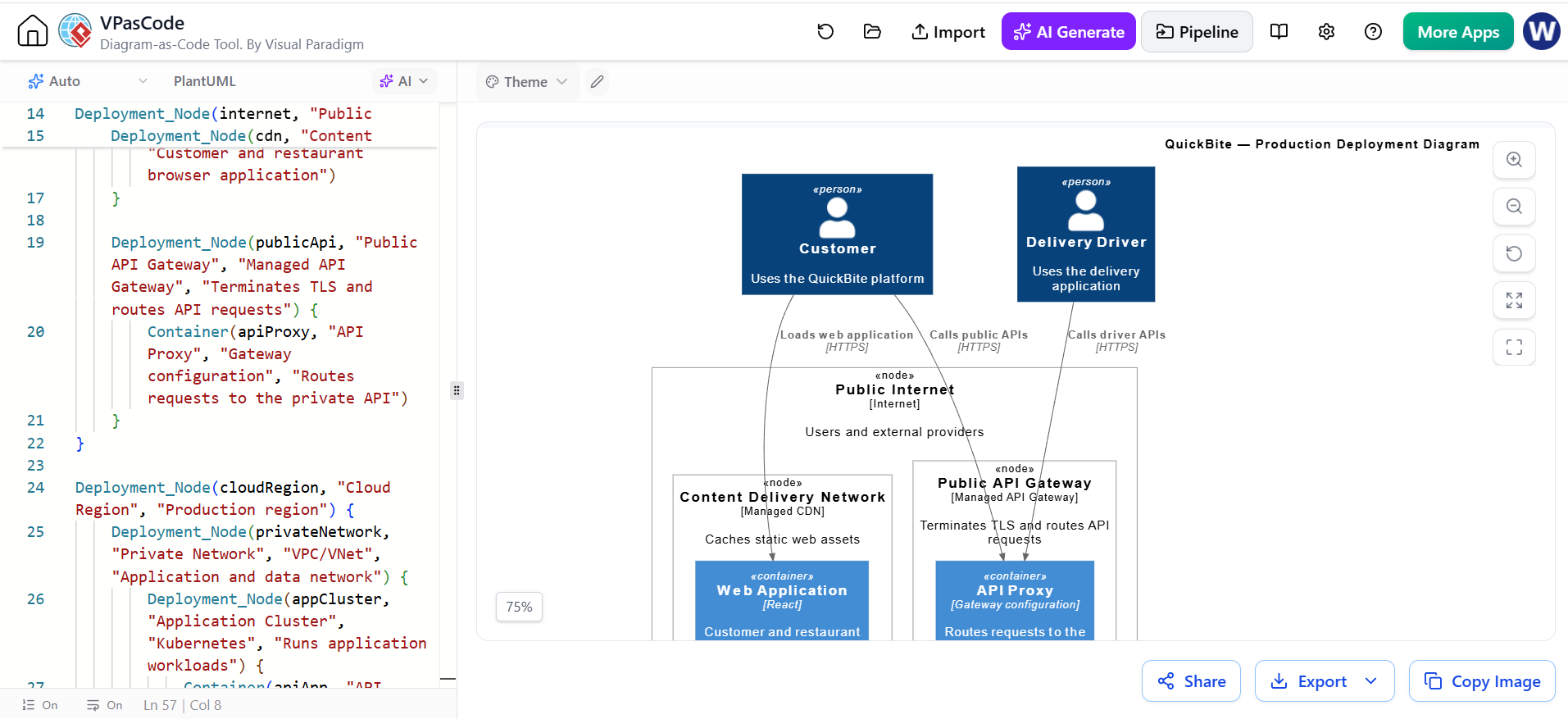
@startuml QuickBite-Deployment

!include https://raw.githubusercontent.com/plantuml-stdlib/C4-PlantUML/master/C4_Deployment.puml

title QuickBite — Production Deployment Diagram

Person(customer, "Customer", "Uses the QuickBite platform")
Person(deliveryDriver, "Delivery Driver", "Uses the delivery application")

System_Ext(paymentProvider, "Payment Provider", "External payment service")
System_Ext(mappingProvider, "Mapping Provider", "External mapping and routing service")
System_Ext(notificationProvider, "Notification Provider", "External email and SMS service")

Deployment_Node(internet, "Public Internet", "Internet", "Users and external providers") {
    Deployment_Node(cdn, "Content Delivery Network", "Managed CDN", "Caches static web assets") {
        Container(webApp, "Web Application", "React", "Customer and restaurant browser application")
    }

    Deployment_Node(publicApi, "Public API Gateway", "Managed API Gateway", "Terminates TLS and routes API requests") {
        Container(apiProxy, "API Proxy", "Gateway configuration", "Routes requests to the private API")
    }
}

Deployment_Node(cloudRegion, "Cloud Region", "Production region") {
    Deployment_Node(privateNetwork, "Private Network", "VPC/VNet", "Application and data network") {
        Deployment_Node(appCluster, "Application Cluster", "Kubernetes", "Runs application workloads") {
            Container(apiApp, "API Application", "Java, Spring Boot", "Provides REST APIs")
            Container(orderWorker, "Order Processing Worker", "Java, Spring Boot", "Processes order events")
            Container(notificationWorker, "Notification Worker", "Java, Spring Boot", "Sends notification requests")
        }

        Deployment_Node(dataServices, "Managed Data Services", "Cloud-managed services") {
            ContainerDb(orderDb, "Order Database", "PostgreSQL", "Stores operational business data")
            ContainerDb(cache, "Cache", "Redis", "Stores cached and short-lived data")
            ContainerQueue(messageBroker, "Message Broker", "RabbitMQ", "Stores asynchronous application events")
        }
    }
}

Rel(customer, webApp, "Loads web application", "HTTPS")
Rel(customer, apiProxy, "Calls public APIs", "HTTPS")
Rel(deliveryDriver, apiProxy, "Calls driver APIs", "HTTPS")

Rel(apiProxy, apiApp, "Routes API requests", "HTTPS")
Rel(apiApp, orderDb, "Reads and writes business data", "SQL")
Rel(apiApp, cache, "Reads and writes cached data", "Redis protocol")
Rel(apiApp, messageBroker, "Publishes events", "AMQP")

Rel(orderWorker, messageBroker, "Consumes order events", "AMQP")
Rel(orderWorker, orderDb, "Updates order state", "SQL")
Rel(orderWorker, paymentProvider, "Processes payments", "HTTPS/JSON")
Rel(orderWorker, mappingProvider, "Requests routes", "HTTPS/JSON")

Rel(notificationWorker, messageBroker, "Consumes notification events", "AMQP")
Rel(notificationWorker, notificationProvider, "Sends notifications", "HTTPS/JSON")

@enduml
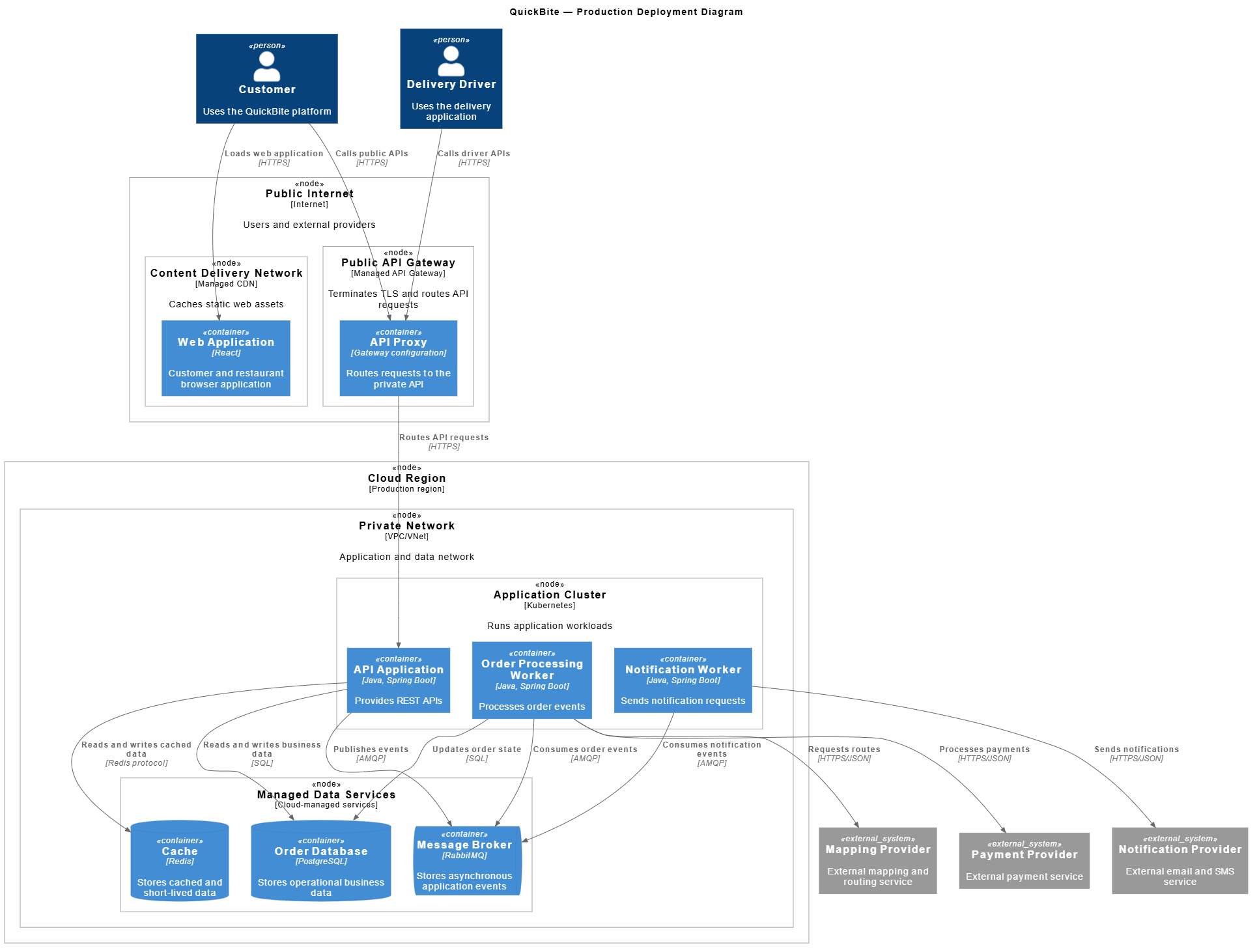
Deployment modeling guidance
Keep deployment diagrams focused on infrastructure decisions that matter. Include details such as:
-
Public versus private network placement
-
Replication
-
Availability zones
-
Kubernetes namespaces
-
Managed services
-
Firewall or gateway boundaries
Do not overload the diagram with every cloud resource unless the diagram is specifically intended for infrastructure operations.
12. Layout and readability
C4-PlantUML supports layout directives and relationship-direction macros.
Common layout directives include:
Relationship-direction variants include:
Rel_U(source, target, "Relationship")
Rel_D(source, target, "Relationship")
Rel_L(source, target, "Relationship")
Rel_R(source, target, "Relationship")
Use direction macros only when they improve readability. Overusing them can make the diagram fragile when elements are added or removed.
Practical layout recommendations
-
Start with
LAYOUT_LEFT_RIGHT(). -
Keep external systems on the outside.
-
Keep the documented system boundary visually central.
-
Avoid crossing relationship lines where possible.
-
Split large diagrams by concern.
-
Prefer several focused diagrams over one dense diagram.
-
Use consistent terminology across all levels.
-
Keep relationship labels short.
-
Use technology labels only where they communicate a meaningful decision.
The C4-PlantUML project documents layout options, relationship positioning, element styling, sprites, and compatibility behavior.
13. Styling and tags
Tags can distinguish elements or relationships by category.
Useful categories include:
-
External systems
-
Deprecated components
-
Security-sensitive components
-
New architecture
-
Legacy architecture
-
Asynchronous relationships
-
Backup or disaster-recovery paths
Complete styling example
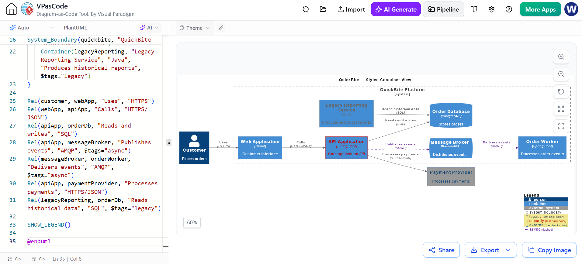
@startuml QuickBite-Styled-Containers

!include https://raw.githubusercontent.com/plantuml-stdlib/C4-PlantUML/master/C4_Container.puml

LAYOUT_LEFT_RIGHT()
title QuickBite — Styled Container View

AddElementTag("legacy", $borderColor="#999999", $fontColor="#666666")
AddElementTag("security", $borderColor="#C00000", $fontColor="#C00000")
AddElementTag("external", $borderColor="#4F81BD", $fontColor="#1F4E79")
AddRelTag("async", $lineColor="#7030A0", $textColor="#7030A0", $lineStyle=DashedLine())

Person(customer, "Customer", "Places orders")
System_Ext(paymentProvider, "Payment Provider", "Processes payments", $tags="external")

System_Boundary(quickbite, "QuickBite Platform") {
    Container(webApp, "Web Application", "React", "Customer interface")
    Container(apiApp, "API Application", "Spring Boot", "Core application API", $tags="security")
    Container(orderWorker, "Order Worker", "Spring Boot", "Processes order events")
    ContainerDb(orderDb, "Order Database", "PostgreSQL", "Stores orders")
    ContainerQueue(messageBroker, "Message Broker", "RabbitMQ", "Distributes events")
    Container(legacyReporting, "Legacy Reporting Service", "Java", "Produces historical reports", $tags="legacy")
}

Rel(customer, webApp, "Uses", "HTTPS")
Rel(webApp, apiApp, "Calls", "HTTPS/JSON")
Rel(apiApp, orderDb, "Reads and writes", "SQL")
Rel(apiApp, messageBroker, "Publishes events", "AMQP", $tags="async")
Rel(messageBroker, orderWorker, "Delivers events", "AMQP", $tags="async")
Rel(apiApp, paymentProvider, "Processes payments", "HTTPS/JSON")
Rel(legacyReporting, orderDb, "Reads historical data", "SQL", $tags="legacy")

SHOW_LEGEND()

@enduml
Use color sparingly. A diagram should remain understandable when printed in grayscale or viewed by someone with color-vision deficiencies.
14. A Git-friendly project structure
A practical repository structure might be:
architecture/
├── README.md
├── context/
│   └── quickbite-system-context.puml
├── containers/
│   └── quickbite-containers.puml
├── components/
│   └── quickbite-api-components.puml
├── dynamic/
│   └── quickbite-place-order.puml
├── deployment/
│   └── quickbite-production.puml
├── code/
│   └── quickbite-order-code.puml
└── rendered/
    ├── quickbite-system-context.svg
    ├── quickbite-containers.svg
    ├── quickbite-api-components.svg
    ├── quickbite-place-order.svg
    └── quickbite-production.svg
Keep source files under version control. Rendered images may also be committed when required by documentation systems, but the .puml source should remain the authoritative artifact.
A useful file header is:
@startuml QuickBite-Containers

' Owner: Payments and Ordering Team
' Audience: Engineering and Operations
' Scope: QuickBite Platform
' Last reviewed: 2026-09-14
' Source of truth: architecture/containers/quickbite-containers.puml

!include https://raw.githubusercontent.com/plantuml-stdlib/C4-PlantUML/master/C4_Container.puml
15. Validation checklist
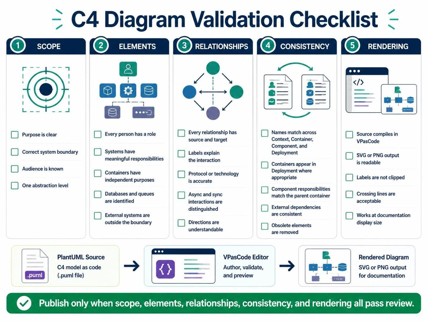
Before publishing a diagram, inspect it at four levels.
Scope
-
Is the diagram’s purpose clear?
-
Is the correct system boundary shown?
-
Is the audience known?
-
Is the diagram showing one abstraction level?
Elements
-
Does every person have a role?
-
Does every system have a meaningful responsibility?
-
Does every container have an independently meaningful purpose?
-
Are databases and queues correctly identified?
-
Are external systems outside the relevant boundary?
Relationships
-
Does every relationship have a source and target?
-
Does the label explain the interaction?
-
Is the protocol or technology accurate?
-
Are asynchronous interactions distinguished from synchronous calls?
-
Are relationship directions understandable?
Consistency
-
Are names consistent between Context, Container, Component, and Deployment diagrams?
-
Does every container in the Container diagram appear in the Deployment diagram where appropriate?
-
Do component responsibilities match their parent container?
-
Are external dependencies represented consistently?
-
Are obsolete elements removed?
Rendering
-
Does the source compile successfully in VPasCode?
-
Does the output remain readable when exported to SVG or PNG?
-
Are labels clipped?
-
Are crossing lines acceptable?
-
Does the diagram work in a documentation page at its displayed size?
16. Common mistakes
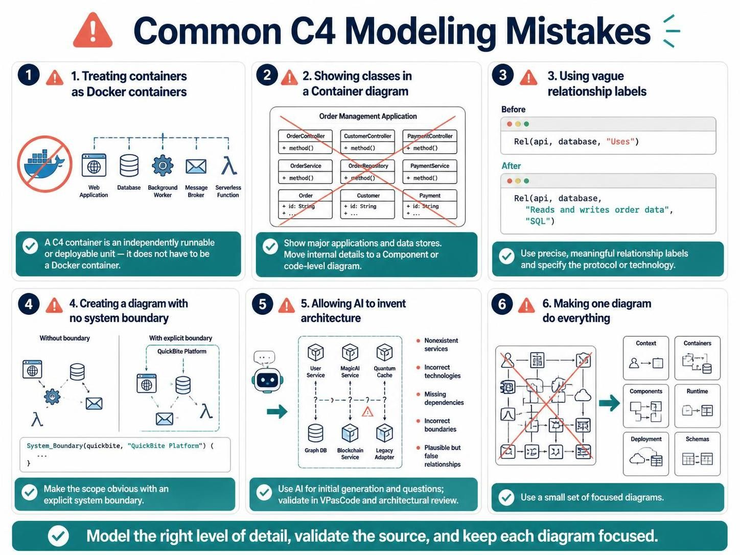
Mistake 1: Treating containers as Docker containers
In C4, a container means an independently runnable or deployable unit. It may be:
-
A web application
-
A database
-
A background worker
-
A message broker
-
A serverless function
It does not have to be a Docker container.
Mistake 2: Showing classes in a Container diagram
A Container diagram should show major applications and data stores, not controllers, repositories, or domain objects.
Move those details to a Component or code-level diagram.
Mistake 3: Using vague relationship labels
Replace:
Rel(api, database, "Uses")
with:
Rel(api, database, "Reads and writes order data", "SQL")
Mistake 4: Creating a diagram with no system boundary
A C4 diagram should make the scope obvious. Use:
System_Boundary(quickbite, "QuickBite Platform") {
    ...
}
Mistake 5: Allowing AI to invent architecture
AI-generated diagrams can introduce:
-
Nonexistent services
-
Incorrect technologies
-
Missing dependencies
-
Incorrect boundaries
-
Relationships that are plausible but false
Use the Visual Paradigm AI Chatbot for initial generation and iterative questioning, then use VPasCode and architectural review to establish the authoritative version.
Mistake 6: Making one diagram do everything
A single diagram should not simultaneously explain:
-
Business context
-
Containers
-
Components
-
Runtime behavior
-
Deployment topology
-
Database schemas
Use a small set of focused diagrams.
17. Recommended AI-assisted workflow
Step 1: Describe the system
Provide the AI Chatbot with:
-
Business purpose
-
Users
-
External systems
-
Major capabilities
-
Known constraints
Step 2: Generate the System Context diagram
Ask for a complete C4-PlantUML file.
Step 3: Validate the boundary
Confirm:
-
What belongs to the system
-
What is external
-
Which users are relevant
-
Which integrations are real
Step 4: Generate the Container diagram
Use the approved Context model as input. Ask the AI to decompose the system into deployable units.
Step 5: Open in VPasCode
Correct:
-
Aliases
-
Relationships
-
Technology labels
-
Layout
-
Styling
-
Include statements
Step 6: Generate Component diagrams selectively
Only expand containers that require deeper explanation.
Step 7: Add dynamic and deployment views
Use these to document important runtime scenarios and infrastructure decisions.
Step 8: Review through pull requests
Architecture changes should be reviewable like source-code changes. Reviewers should check:
-
Boundary changes
-
New dependencies
-
Data ownership
-
Failure behavior
-
Security implications
-
Deployment impact
Step 9: Render and publish
Export SVG for documentation where possible because it scales better than PNG. Store the source alongside the rendered output.
18. Reusable prompt templates
System Context prompt
Generate a complete C4-PlantUML System Context diagram for [SYSTEM NAME].

Purpose:
[BUSINESS PURPOSE]

People:
- [PERSON]: [ROLE]
- [PERSON]: [ROLE]

External systems:
- [SYSTEM]: [RESPONSIBILITY]
- [SYSTEM]: [RESPONSIBILITY]

Relationships:
- [SOURCE] [ACTION] [TARGET]
- [SOURCE] [ACTION] [TARGET]

Requirements:
- Use C4_Context.puml.
- Show one system boundary only.
- Exclude internal services, databases, classes, and implementation details.
- Include protocols only where meaningful.
- Return complete executable PlantUML code.
Container prompt
Generate a complete C4-PlantUML Container diagram for [SYSTEM NAME].

Use the following system context:
[PASTE APPROVED CONTEXT DESCRIPTION]

Containers:
- [CONTAINER]: [TECHNOLOGY]: [RESPONSIBILITY]
- [CONTAINER]: [TECHNOLOGY]: [RESPONSIBILITY]
- [DATABASE]: [TECHNOLOGY]: [DATA OWNERSHIP]
- [QUEUE]: [TECHNOLOGY]: [EVENT PURPOSE]

Show:
- Users calling applications
- Applications calling APIs
- Services reading and writing data
- Synchronous and asynchronous relationships
- External system integrations

Use C4_Container.puml and return a complete PlantUML file.
Component prompt
Generate a complete C4-PlantUML Component diagram for the [CONTAINER NAME].

Container responsibility:
[DESCRIPTION]

Components:
- [COMPONENT]: [RESPONSIBILITY]
- [COMPONENT]: [RESPONSIBILITY]
- [COMPONENT]: [RESPONSIBILITY]

External dependencies:
- [DEPENDENCY]: [PURPOSE]

Show:
- Component responsibilities
- Dependency direction
- Persistence and messaging adapters
- External integrations

Do not generate individual classes unless explicitly requested.
Return complete executable PlantUML source.
Review prompt
Review this C4-PlantUML diagram as a software architect.

Check:
- Correct C4 abstraction level
- Scope and system boundaries
- Missing or misleading relationships
- Inconsistent terminology
- Technology labels
- Excessive detail
- Layout readability
- Syntax problems

Return:
1. Findings
2. Recommended changes
3. A corrected complete PlantUML file
19. Final recommendations
Use the Visual Paradigm AI Chatbot to accelerate exploration, ask architecture questions, generate initial C4 views, and refine diagrams conversationally. Use VPasCode as the controlled editing and rendering environment for complete source files. Keep the resulting PlantUML in version control and review it alongside application changes.
The most maintainable C4 documentation usually consists of:
-
One System Context diagram
-
One Container diagram per major system
-
Component diagrams only for important containers
-
Dynamic diagrams for key scenarios
-
Deployment diagrams for operational topology
-
Code diagrams only where implementation detail adds value
The C4-PlantUML repository provides the macros and examples needed to implement these views in PlantUML, while Visual Paradigm’s tooling connects natural-language generation with diagram-as-code editing and export workflows.
References
-
From Big Picture to Code: A Beginner’s Guide to Visualizing Software Architecture with the C4 Model: Step-by-step beginner tutorial covering all four C4 levels with practical PayQuick payment platform examples and PlantUML code snippets.
-
Mastering the AI + C4 Model + Diagram as Code: A Hybrid Approach to Software Architecture Diagrams: Explains why Visual Paradigm remains essential for professional architects and presents a hybrid workflow combining AI, C4, and diagram-as-code.
-
The Ultimate Guide to C4-PlantUML Studio: Revolutionizing Software Architecture Design: Comprehensive guide covering AI-powered generation, step-by-step workflows, real-world use cases, and why Visual Paradigm leads the market.
-
Mastering Software Architecture with the C4 Model and Visual Paradigm: Evaluation of Visual Paradigm’s C4 ecosystem including hierarchical navigation, living documentation integration, and practical workflow for linking context to container diagrams.
-
Architecting Smart Infrastructure: A C4 Model Case Study of an EV Charging Network Using Visual Paradigm’s AI-Powered Tools: Real-world case study demonstrating AI-powered C4 generation for an EV charging network with measurable outcomes.
Related posts:
 Comprehensive Guide to the C4 Model for Software Architecture Documentation
 Integrating C4 and UML Diagrams: A Synergistic Approach to Software Architecture with Visual Paradigm
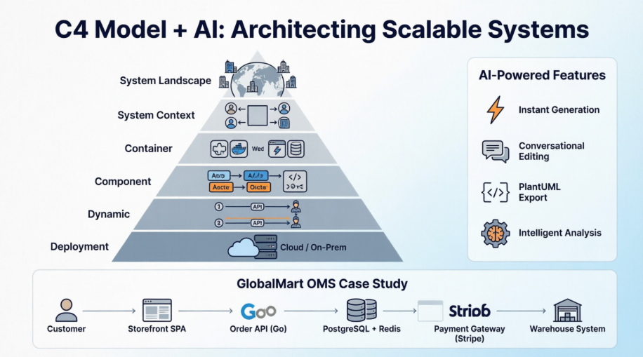 A Practical Guide to C4 Modeling with AI-Powered Visual Paradigm Tools: Architecting Scalable E-Commerce Systems
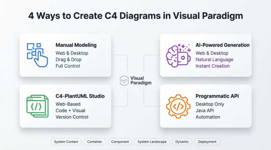 A Comprehensive Case Study on Building C4 Diagrams with Visual Paradigm’s Multi-Method Approach

 English
 Arabic
 Chinese (Simplified)
 Dutch
Dutch French
 German
 Italian
 Japanese
 Korean
 Portuguese
 Russian
 Spanish