


In the realm of Business Process Model and Notation (BPMN), controlling the flow of work is critical. One of the most powerful constructs for managing complex workflows is the Parallel Gateway. This symbol allows processes to branch out into multiple simultaneous activities and then synchronize them back into a single path.
This tutorial provides a deep dive into the Parallel Gateway, specifically focusing on how to implement AND-split (forking) and AND-join (synchronization) logic using the Visual Paradigm modeling tool. We will analyze a standard “Order Fulfillment” scenario to illustrate these concepts clearly.
Understanding the Parallel Gateway Symbol
The Parallel Gateway is represented by an orange diamond shape containing a plus sign (+). Unlike the Exclusive Gateway (XOR), which routes a process down a single path based on a condition, the Parallel Gateway is “AND” logic. It dictates that all outgoing paths must be executed simultaneously.
In BPMN specifications, this gateway serves two primary functions:
- AND-Split (Fork): One incoming sequence flow triggers multiple outgoing flows simultaneously. The process splits into parallel threads.
- AND-Join (Join): Multiple incoming sequence flows converge. The process waits until all incoming threads have arrived before proceeding to the next step.
Case Study: The Order Fulfillment Process
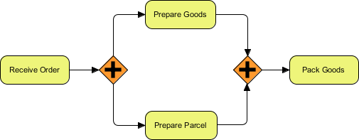
To visualize this, let’s examine the system architecture of a typical e-commerce order fulfillment workflow. The goal is to process an order efficiently by performing non-dependent tasks in parallel.
1. The Trigger: Receiving the Order
The process begins with a task labeled Receive Order. This is a standard Task in BPMN. Once this task is completed, the process flow moves to the first Parallel Gateway.
2. The AND-Split: Preparing Goods and Parcelling
Upon reaching the first Parallel Gateway (the first orange diamond with the plus sign), the logic forks. The system does not wait to finish one task before starting the other. Instead, it initiates both tasks simultaneously:
- Prepare Goods: Warehouse staff pick and pack the specific items ordered.
- Prepare Parcel: Logistics staff prepare the shipping documentation, label the box, and arrange the courier.
Because these two activities are independent, running them in parallel significantly reduces the total lead time compared to a sequential approach.
3. The AND-Join: Synchronization
After both parallel threads are executed, the flow lines converge at the second Parallel Gateway. This is the AND-Join. The system now enforces a synchronization barrier. The process will not proceed to the next step until both Prepare Goods AND Prepare Parcel are finished.
Once the synchronization point is reached, the flow moves to the final task: Pack Goods (or “Pack and Ship”), ensuring that the physical goods and the shipping logistics are ready before the final dispatch occurs.
Implementing This in Visual Paradigm
When using Visual Paradigm to create this model, the tooling automatically handles the logic once the shape is placed on the canvas. Here is how you can structure your project and diagram:
Step 1: Create the Project Structure
Start by creating a new BPMN project within Visual Paradigm. Ensure that you are working within the BPMN 2.0 profile to access the full range of gateways.
Step 2: Place the Parallel Gateway
Drag the Parallel Gateway from the Palette onto your diagram. It is crucial to select the correct symbol—the one with the plus sign (+)—and not the Xor or Or gateways.
Step 3: Connect the Flows
Connect your tasks using Sequence Flows. Visual Paradigm will automatically validate the logic. If you connect multiple outgoing paths from a Parallel Gateway, the tool interprets this as an AND-Split. If you connect multiple incoming paths to a Parallel Gateway, it interprets this as an AND-Join.
Step 4: Validate the Model
Before finalizing your diagram, use the Process Validator feature in Visual Paradigm. This tool checks for common modeling errors, such as an unbalanced split or join, ensuring that your AND-Split is correctly balanced by an AND-Join.
Why Parallelism Matters
The efficiency of the “Order Fulfillment” process relies entirely on the Parallel Gateway. If the system used an Exclusive Gateway (XOR) instead, it would have to choose either “Prepare Goods” OR “Prepare Parcel,” which would break the process logic. If it used a sequential task flow, it would wait for “Prepare Goods” to finish completely before starting “Prepare Parcel.”
By utilizing the Parallel Gateway in Visual Paradigm, you accurately model real-world concurrency, ensuring that the business process is optimized for speed and resource utilization.
Conclusion
The Parallel Gateway is a fundamental building block for complex business processes. By mastering the AND-Split and AND-Join logic, you can design systems that execute tasks simultaneously, reducing bottlenecks and improving overall throughput. Visual Paradigm provides the robust tooling necessary to model these complex interactions clearly and accurately.

 English
 Arabic
 Chinese (Simplified)
 Dutch
Dutch French
 German
 Italian
 Japanese
 Korean
 Portuguese
 Russian
 Spanish