


Business Process Model and Notation (BPMN) is the industry standard for visualizing complex business workflows. By using a standardized set of symbols, organizations can bridge the gap between business stakeholders and technical developers. This tutorial explores a classic Order Fulfillment process, demonstrating how to structure a workflow that spans multiple departments and how to use visual grouping tools to maintain clarity in your diagrams.
The Architecture of the Order Fulfillment Process
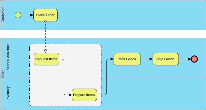
The diagram below illustrates a seamless interaction between a customer and internal operations. The process is divided into vertical sections known as Pools and Swimlanes, which act as the structural backbone of any BPMN diagram.
- Customer Pool: Represents the external entity initiating the transaction. The process begins here.
- Service Assistant Pool: The internal process owner responsible for managing the request.
- Shop & Inventory Swimlanes: These represent specific roles or departments within the organization. They define who is responsible for executing each task.
Step 1: Initiating the Transaction
The workflow starts with a Start Event (the green circle) located in the Customer pool. This signifies that the process is triggered by an external action: the customer placing an order. In BPMN, this is often represented as a Message Flow connecting the Customer to the Service Assistant.
Step 2: Handling the Request
Once the order is received, the Service Assistant receives the request. The diagram shows a dashed line connecting the “Place Order” task to the “Request Items” task. This dashed line represents a Message Flow, indicating communication between different participants (Customer and Service Assistant) rather than a sequential execution of tasks.
Visualizing Complexity with Groups
As processes grow, they can become cluttered. To solve this, BPMN offers the Group element. In the diagram, you will see a dashed rectangle surrounding “Request Items” and “Prepare Items”.
What is a Group?
A Group is a visual container used to cluster related elements. It is strictly for documentation purposes. Unlike a Subprocess, a Group does not execute logic, contain its own flow, or have a start/end event. It serves to:
- Visually cluster related elements for documentation purposes.
- Indicate that tasks belong to a specific logical scope (e.g., “Inventory Management”).
- Improve diagram readability without altering the process logic.
Step 3: The Inventory Workflow
Inside the visual grouping, we see the operational logic:
- Request Items: The Service Assistant initiates a request to the Inventory.
- Prepare Items: The Inventory lane receives the request and prepares the goods. The solid line indicates a direct sequence flow between these tasks.
Step 4: Completion
Once the items are prepared, the flow moves back to the Service Assistant to “Pack Goods” and “Ship Goods”. The process concludes with a End Event (the red circle), signaling the successful completion of the order fulfillment cycle.
Tooling for Process Modeling
To create professional-grade diagrams like the one above, you need robust modeling software. The workflow described here was modeled using Visual Paradigm, a comprehensive tool for BPMN 2.0 compliance.
Why Visual Paradigm?
- Drag-and-Drop Interface: Easily place Pools, Swimlanes, and Groups.
- Tooling: Visual Paradigm BPMN Tool: Features an intuitive palette that guides users through the correct syntax rules, ensuring your diagrams are valid and executable.
- Documentation Support: The tool allows for the easy creation of Groups and Notes, making it ideal for technical documentation and system architecture visualization.
By mastering these elements, you can transform complex business requirements into clear, actionable technical diagrams.

 English
 Arabic
 Chinese (Simplified)
 Dutch
Dutch French
 German
 Italian
 Japanese
 Korean
 Portuguese
 Russian
 Spanish