


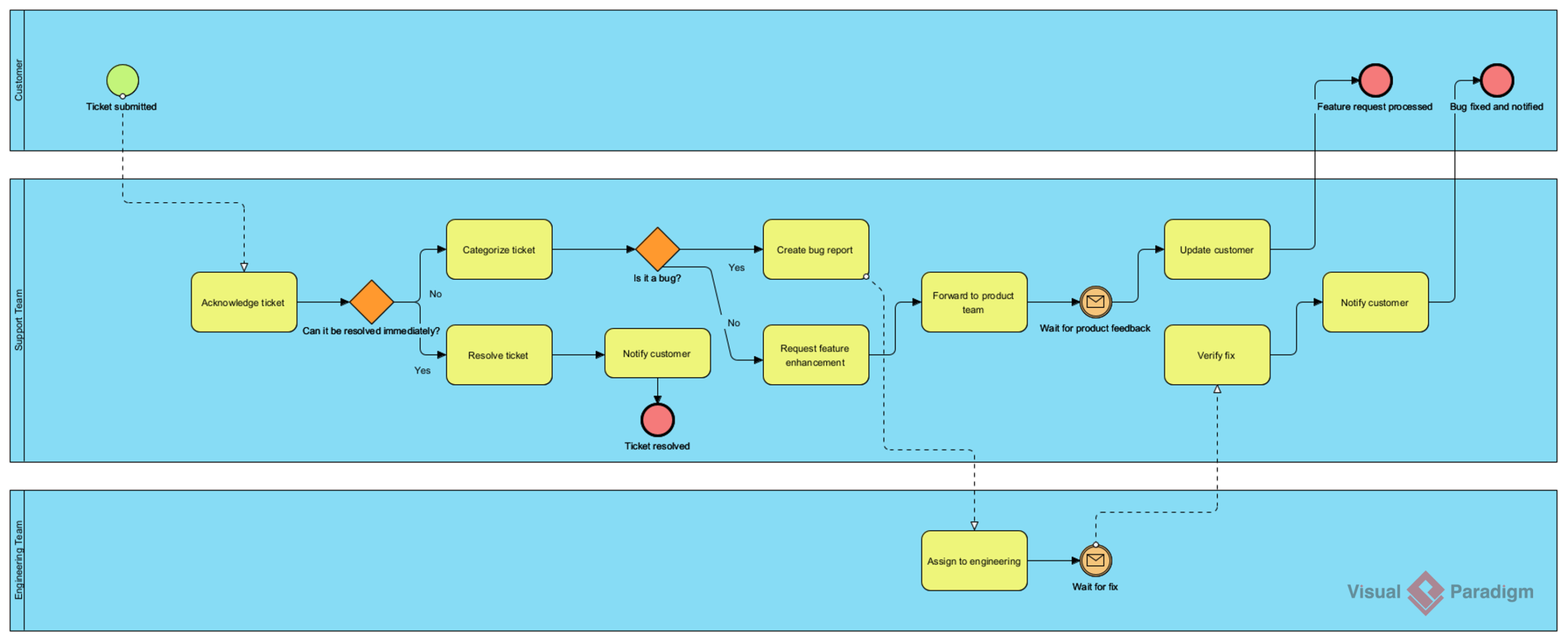
In the fast-paced world of Software-as-a-Service (SaaS), the efficiency of your customer support infrastructure directly correlates with customer retention and satisfaction. This tutorial explores a comprehensive Customer Support Ticket Resolution Process, modeled using Visual Paradigm’s BPMN (Business Process Model and Notation) capabilities. We will dissect how a SaaS company orchestrates interactions between Customers, Support Staff, and Engineering teams to ensure every issue is tracked, categorized, and resolved.
Architecting the Workflow: The Role of Swimlanes
The foundation of this diagram is its structural organization. Visual Paradigm utilizes Swimlanes (or Pools) to clearly delineate responsibilities. This visual separation prevents ambiguity by assigning specific tasks to the correct department.
- Customer Lane (Top): Represents the external actor. This lane initiates the process and receives final notifications. It contains the Start Event (Ticket Submitted) and the End Events (Feature Request Processed, Bug Fixed).
- Support Team Lane (Middle): The central processing hub. This lane handles the initial intake, triage, categorization, and customer communication. It contains the majority of the decision logic and manual tasks.
- Engineering Team Lane (Bottom): The backend execution layer. This lane is responsible for the actual technical work—fixing bugs or implementing feature requests—triggered only when the support team determines a deeper technical intervention is required.
Step-by-Step Process Analysis
1. Initiation and Triage
The process begins when the Customer submits a ticket. This event triggers a dashed “Message Flow” (indicated by the dotted line) to the Support Team. The first action for Support is to Acknowledge Ticket. Immediately following this, the process encounters an Inclusive Gateway asking: “Can it be resolved immediately?”
This decision point splits the flow into two paths:
- Yes: The issue is simple. The agent proceeds to Resolve Ticket, notifies the customer, and the process concludes with the Ticket Resolved end event.
- No: The issue is complex. The flow moves to Categorize Ticket.
2. Categorization and Routing
Once categorized, the process hits a second decision gateway: “Is it a bug?”. This is crucial for routing efficiency.
Scenario A: It is a Bug
If the ticket is a software defect, the system directs the workflow to Create Bug Report. This action acts as a bridge to the Engineering Team. A dashed line connects the Support Lane to the Engineering Lane, specifically to the Assign to Engineering task. This demonstrates a cross-lane handoff.
Scenario B: It is a Feature Request
If the ticket is a new feature or enhancement, the workflow moves to Request Feature Enhancement. This is then forwarded to the Product Team for evaluation.
3. The Engineering Loop
Once assigned to Engineering, the process enters a waiting state (represented by the Wait for fix message event). The Engineering team performs the fix, and the flow returns to the Support Team via a dashed line to the Verify Fix task. This ensures that the person who received the customer’s complaint is the one verifying the solution before the customer is notified.
4. Closing the Loop
After verification, the Support Team updates the customer. From here, the path depends on the original categorization:
- If it was a Feature Request, the process ends at Feature Request Processed.
- If it was a Bug, the process ends at Bug Fixed and Notified.
Key Technical Concepts in Visual Paradigm
Message Flows vs. Sequence Flows
One of the most common modeling errors is using a standard arrow (Sequence Flow) to connect tasks across different lanes. In Visual Paradigm, it is critical to distinguish between:
- Sequence Flows (Solid Lines): Used for internal steps within the same lane (e.g., Acknowledge Ticket → Can it be resolved immediately?).
- Message Flows (Dashed Lines): Used strictly for communication between different lanes or pools. Notice the dashed lines connecting the Customer to Support, and Support to Engineering. This adheres to BPMN 2.0 standards and visually communicates that data or control is being passed between distinct entities.
Event-Based Gateways
The diagram utilizes specific event markers, such as the Message Event (envelope icon) in the Engineering lane. This represents a “Wait” state. In a static diagram, it looks like a pause, but in Visual Paradigm, this can be configured to represent a specific duration or a trigger event (e.g., “When the code is merged”).
Conclusion
This diagram exemplifies a robust, scalable process architecture. By utilizing swimlanes to separate concerns and strict BPMN gateways to direct logic, Visual Paradigm allows teams to visualize the entire lifecycle of a customer request. Whether it is a simple resolution or a complex engineering fix, the process ensures accountability and clear communication channels.
Implementing this logic in Visual Paradigm not only creates a visual guide for your staff but also serves as a blueprint for automation tools, ensuring that no ticket gets lost in the translation between Support and Engineering.

 English
 Arabic
 Chinese (Simplified)
 Dutch
 French
 German
 Italian
 Japanese
 Korean
 Portuguese
 Russian
 Spanish