


Introduction
In the complex world of business process modeling, it is easy to get lost in the minutiae of task sequences and gateways. However, before diving into the granular details of how a process works, stakeholders often need to understand who is talking to whom. This is where BPMN Conversation Diagrams shine.
Unlike traditional flowcharts that focus on internal logic, Conversation Diagrams provide a high-level “bird’s-eye view” of collaborative relationships. They strip away the noise of individual tasks to reveal the essential message exchanges between participants—whether they are departments, external partners, or software systems.
This guide explores the core concepts of BPMN Conversation Diagrams, analyzes their key components, and walks you through a practical, step-by-step tutorial on creating a logistics system diagram. Whether you are a business analyst, solution architect, or product manager, mastering this notation will help you define scope, manage complexity, and communicate system architecture more effectively.
What is a BPMN Conversation Diagram?
A Conversation diagram in BPMN (Business Process Model and Notation) is designed to provide a high-level overview of the message exchanges that occur between participants in a system. While standard process diagrams focus on sequence and flow, Conversation diagrams focus on the collaborative relationships and the logical grouping of interactions.
Think of it as the social network map of your business process. It doesn’t tell you what someone says in every sentence, but it clearly shows who is connected to whom and the nature of their relationship.
Key Components and Concepts
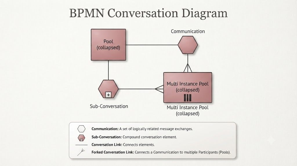
To build effective conversation diagrams, you need to understand the four primary elements used to construct them. These elements allow you to model everything from simple one-on-one exchanges to complex multi-party negotiations.
-
Communication: Represented by a hexagon, this element defines a set of logically related message exchanges. It is the core unit of interaction in the diagram.
-
Sub-Conversation: A compound conversation element identified by a + symbol inside the hexagon. This is used to group multiple communications together, allowing you to hide complexity and keep the high-level view clean.
-
Conversation Link: A simple line used to connect Communications to Participants. It represents the channel through which messages flow.
-
Forked Conversation Link: A specialized link that connects a single Communication to multiple Participants simultaneously. This is crucial for modeling scenarios where one message or agreement involves several parties at once.
Visual Example Analysis
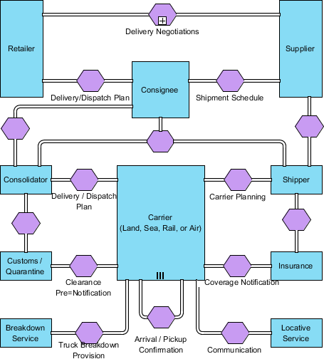
When looking at a well-constructed conversation diagram, such as the reference example provided in image_a4d188.png, you can see how these elements interact to tell a story of collaboration.
| Element | Description |
|---|---|
| Pools | Represent the participants involved in the conversation. These can be collapsed pools (representing an entire organization) or specific Multi-Instance pools. |
| Connections | The diagram demonstrates how individual Pools link to standard Communications. In more complex scenarios, participants may link through a Sub-Conversation to indicate a broader relationship. |
| Multi-Instance | The use of vertical bars (as seen in the “Multi Instance Pool”) indicates an entity that handles multiple simultaneous instances of the process. This is common in scenarios involving multiple vendors or customers. |
Usage Cases
Conversation diagrams are not meant to replace detailed process flows. Instead, they serve specific strategic purposes in the modeling lifecycle:
-
System Architecture Mapping: When you need to visualize the big picture of how different services, departments, or external partners communicate without getting bogged down in the specific sequence of tasks.
-
Scope Definition: Defining the boundaries of a collaborative system by identifying which participants are involved in specific sets of message exchanges. This helps prevent scope creep early in a project.
-
Complex Interaction Management: Using Sub-Conversations to organize and hide the complexity of intricate, multi-step message protocols, making the high-level design easier to understand for non-technical stakeholders.
-
Multi-Party Coordination: When a single business requirement involves multiple stakeholders, the Forked Conversation Link helps clarify that a specific message exchange involves several entities at once, such as a contract signing involving a buyer, seller, and legal witness.
How to Draw a BPMN Conversation Diagram: A Step-by-Step Tutorial
To demonstrate how these concepts come to life, we will create a simple conversation diagram for a logistics system. This example involves a Retailer, Supplier, Consignee, Shipper, and other logistics partners.
Getting Started
-
Create a new project by selecting Project > New from the application toolbar. In the New Project window, enter Logistic System as the project name and click Create Blank Project.
-
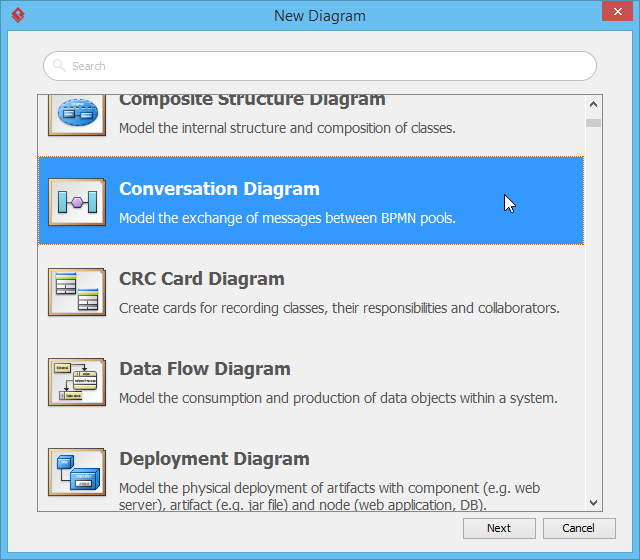
Create a conversation diagram by selecting Diagram > New from the application toolbar. In the New Diagram window, select Conversation Diagram and click Next.
-
Leave the diagram name unchanged and click OK to create the diagram.
Adding Participants and Conversations
-
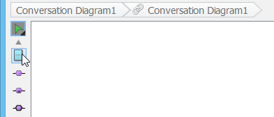
Let’s start by creating a participant. Select Participant from the diagram toolbar.
-
Click on the diagram to create a participant. Enter Retailer as the name and press Enter to confirm.

-
Move the mouse pointer over the Retailer participant.

-
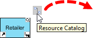
Press and drag the Resource Catalog icon (at the top right of the shape) to an empty space on the diagram.
-
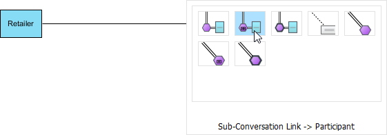
Release the mouse button and select Sub-Conversation Link -> Participant from the Resource Catalog to create a new participant.
-
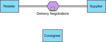
Enter Supplier as the name of the new participant and press Enter. Then, enter Delivery Negotiations as the name of the sub-conversation (the purple shape in the middle) and press Enter again.

-
Select Participant from the diagram toolbar again and click below the Delivery Negotiations sub-conversation to create another participant. Name it Consignee.
Creating Links and Refining the Diagram
-
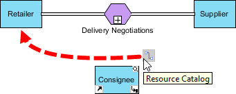
Move the mouse pointer over the Consignee participant. Press and drag the Resource Catalog icon to the Retailer participant to create a link between them.
-
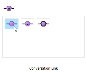
Select Conversation Link from the Resource Catalog.
-
Enter Delivery/Dispatch Plan as the name of the conversation link and press Enter. If the new shape overlaps with others, drag it to a different position to tidy up the diagram.
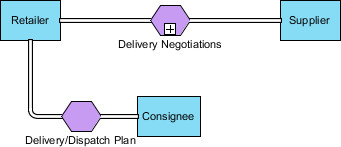
-
Repeat the previous steps to create a conversation link between Consignee and Supplier. Name this communication Shipment Schedule.
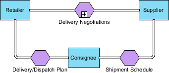
-
Resize the Retailer and Supplier participants to make them taller.
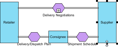
-
Use the Resource Catalog to create a new participant named Shipper from the Supplier participant, with a conversation link in between. Then, create another participant named Insurance from the Shipper participant.
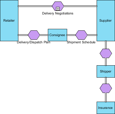
-
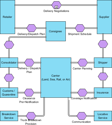
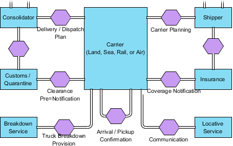
Continue drawing the conversation diagram until it looks like the one below. You can use the techniques you have learned so far. Note that you can add a line break when naming a shape by pressing Alt + Enter.
-
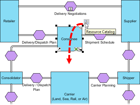
Move the mouse pointer over the Consignee participant. Press and drag the Resource Catalog icon to the empty space below the participant.
-
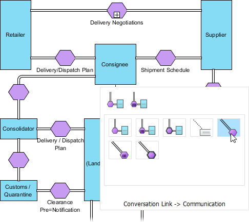
Release the mouse button and select Conversation Link -> Communication from the Resource Catalog.
-
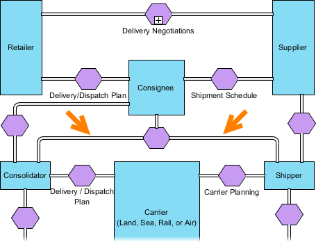
Connect the newly created communication, the Consolidator participant, and the Shipper participant with a conversation link using the Resource Catalog.
Advanced Features: Self-Links and Multiplicity
-
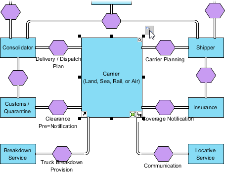
Move the mouse pointer over the Carrier (Land, Sea, Rail, or Air) participant. Click on the Resource Catalog icon (don’t drag it this time).
-
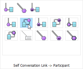
Select Self Conversation Link -> Participant from the Resource Catalog.
-
Enter Arrival / Pickup Confirmation as the name of the communication and press Enter to confirm.
-
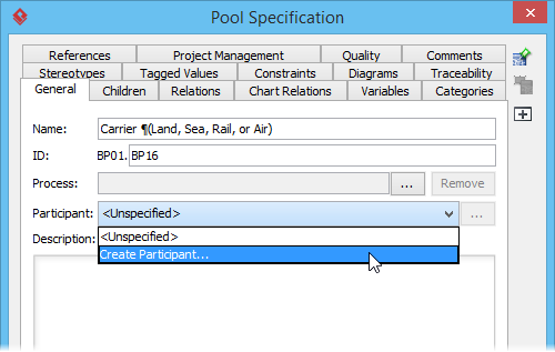
Nearly done. Right-click on the Carrier (Land, Sea, Rail, or Air) participant and select Open Specification… from the popup menu.
-
Click on the drop-down menu for Participant and select Create Participant….
-
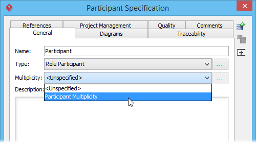
In the Participant Specification window, select Participant Multiplicity as Multiplicity and click OK to confirm.
-
Click OK to close the Pool Specification window and return to the diagram. Your final diagram should look like this:
Conclusion
BPMN Conversation Diagrams are a powerful tool for simplifying the complex web of business interactions. By focusing on the “who” and “what” of message exchanges rather than the “when” and “how,” they provide clarity in the early stages of system design and stakeholder alignment.
Whether you are mapping out a new logistics network, defining API integrations between microservices, or clarifying roles in a cross-departmental workflow, conversation diagrams offer a clean, intuitive way to visualize collaboration. By mastering the use of Communications, Sub-Conversations, and Forked Links, you can create models that are not only accurate but also easily understood by both technical and non-technical audiences.
Start small, focus on the key participants, and let the diagram evolve as your understanding of the business relationships deepens.
References
- Introduction to BPMN: A foundational guide to understanding the basics of Business Process Model and Notation, including its various diagram types and core concepts.
- How to Define Working Procedures for Business Tasks: A tutorial on defining and documenting working procedures for business tasks, helping to streamline operations and improve efficiency.




 English
 Arabic
 Chinese (Simplified)
 Dutch
Dutch French
 German
 Italian
 Japanese
 Korean
 Portuguese
 Russian
 Spanish