


Introduction
In today’s rapidly evolving software development landscape, the ability to effectively model and visualize system architecture before implementation is crucial for project success. Object-oriented design serves as the foundation for building robust, scalable, and maintainable software systems. Among the various modeling techniques available, UML (Unified Modeling Language) class diagrams stand out as one of the most powerful tools for representing the static structure of a system.
This comprehensive case study explores the practical application of Visual Paradigm, a leading UML modeling platform, in designing an Academic Management System. Through this real-world scenario, we will demonstrate how class diagrams serve as blueprints that bridge the gap between conceptual design and actual implementation.
The Academic Management System presents an ideal case study as it encompasses common object-oriented design patterns including inheritance, association, composition, and multiplicity relationships. By following this detailed guide, software architects, developers, and system designers will gain hands-on experience in transforming real-world requirements into professional-grade UML models that facilitate clear communication among stakeholders, reduce development errors, and streamline the implementation process.
Whether you’re a beginner taking your first steps into software modeling or an experienced developer looking to refine your design skills, this case study provides valuable insights into leveraging Visual Paradigm’s comprehensive toolset to create effective, industry-standard class diagrams.
Understanding Class Diagrams: The Foundation of Object-Oriented Design
What is a Class Diagram?
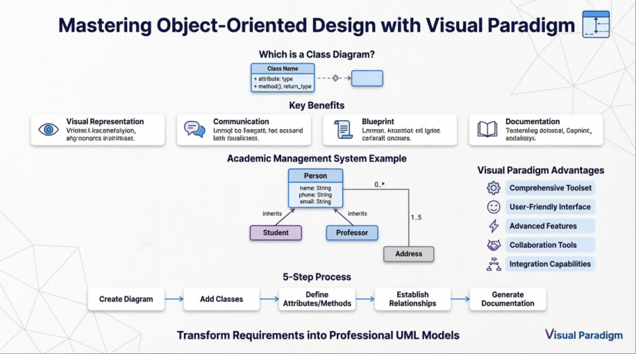
A class diagram is a static structure diagram in UML (Unified Modeling Language) that shows the system’s classes, their attributes, methods (operations), and the relationships between objects. It is used to model the static view of an application.
Why Use a Class Diagram?
-
Visual Representation: Provides a clear visual representation of the system’s structure.
-
Communication: Helps in communicating the design of the system to stakeholders.
-
Blueprint: Acts as a blueprint for the system’s implementation.
-
Documentation: Serves as documentation for the system’s design.
When to Use a Class Diagram?
-
Design Phase: During the design phase of software development to model the system’s structure.
-
Refactoring: When refactoring existing systems to understand and improve the system’s design.
-
Documentation: For documenting the system’s architecture and design.
Visual Paradigm: The Premier UML Modeling Platform
The Best Choice of UML Tool for Developers
When it comes to UML modeling, Visual Paradigm stands out as one of the best choices for developers. Here’s why:
-
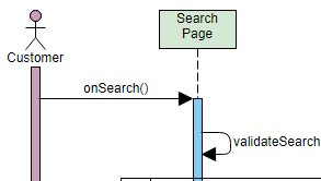
Comprehensive Toolset: Visual Paradigm offers a wide range of diagramming tools, including class diagrams, sequence diagrams, use case diagrams, and more. This comprehensive toolset ensures that you can model every aspect of your system with precision.
-
User-Friendly Interface: With an intuitive and user-friendly interface, Visual Paradigm makes it easy for developers to create and manage complex diagrams. The drag-and-drop functionality and clear layout options streamline the design process.
-
Advanced Features: Visual Paradigm includes advanced features such as code engineering, model-driven architecture (MDA), and agile development support. These features help developers transition seamlessly from design to implementation.
-
Collaboration Tools: Visual Paradigm supports team collaboration with features like version control, teamwork client, and real-time collaboration. This makes it easier for teams to work together on large projects, ensuring consistency and accuracy.
-
Integration Capabilities: Visual Paradigm integrates smoothly with popular development environments and tools, such as Eclipse, Visual Studio, and various version control systems. This integration enhances productivity and ensures a cohesive workflow.
-
Extensive Documentation and Support: Visual Paradigm provides extensive documentation, tutorials, and customer support to help developers get the most out of the tool. Whether you’re a beginner or an experienced user, you’ll find the resources you need to succeed.
Visual Paradigm is not just a UML tool; it’s a comprehensive solution that empowers developers to create high-quality models, collaborate effectively, and streamline the development process. Choose Visual Paradigm for your UML needs and experience the difference it can make in your projects.
Case Study: Designing an Academic Management System
Project Overview
Our case study focuses on designing an Academic Management System for a university. The system needs to manage information about people (students and professors), their addresses, and the relationships between them. This real-world scenario demonstrates fundamental object-oriented design principles and showcases Visual Paradigm’s capabilities.
Requirements Analysis
The system must:
-
Store personal information for all individuals (name, phone, email)
-
Manage address information with validation capabilities
-
Track student-specific data (student number, academic performance)
-
Maintain professor information (salary, staff details, teaching load)
-
Establish relationships between entities (students supervised by professors, people having addresses)
Step-by-Step Implementation Guide
Step 1: Initialize Your Visual Paradigm Project
-
Launch Visual Paradigm.
-
Create a new project or open an existing one.
-
Set up your project structure with appropriate naming conventions.
Step 2: Create a New Class Diagram
-
In the Project Browser, right-click on the project name.
-
Select
New Diagram>Class Diagram. -
Name your diagram (e.g., “Academic System Class Diagram”) and click
OK.
Step 3: Add Core Classes
-
From the Diagram Toolbar, select the
Classtool. -
Click on the diagram canvas to add a new class.
-
Name the class (e.g.,
Person).
Step 4: Define Attributes and Methods for Person Class
-
Double-click on the class to open the Specification window.
-
In the
Attributestab, add the attributes:-
name: str -
phoneNumber: str -
emailAddress: str
-
-
In the
Operationstab, add the methods:-
+purchaseParkingPass(): void
-
Step 5: Build the Complete Class Structure
Repeat steps 3 and 4 to add more classes with their specific attributes and methods:
Address Class:
-
Attributes:
street: str,city: str,state: str,postalCode: int,country: str -
Methods:
+validate(): bool,+outputAsLabel(): str
Student Class:
-
Attributes:
studentNumber: int,averageMark: int -
Methods:
+isEligibleToEnroll(str): bool,+getSeminarsTaken(): int
Professor Class:
-
Attributes:
salary: int,staffNumber: int,yearsOfService: int,numberOfClasses: int -
Methods: (To be defined based on requirements)
Step 6: Establish Relationships Between Classes
-
From the Diagram Toolbar, select the
Associationtool. -
Click on the source class (e.g.,
Person) and drag to the target class (e.g.,Address). -
Define the multiplicity (e.g., 0..1 to 1 for
Personlives atAddress).
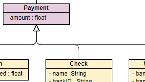
Step 7: Implement Inheritance Hierarchy
-
From the Diagram Toolbar, select the
Generalizationtool. -
Click on the subclass (e.g.,
Student) and drag to the superclass (e.g.,Person). -
Repeat for
Professorclass.
This establishes that both Student and Professor are specialized types of Person, inheriting common attributes and methods.
Step 8: Define Multiplicity and Role Names
-
Double-click on the association line to open the Specification window.
-
Define the multiplicity and roles:
-
Person to Address: 0..* to 1 (a person can have multiple addresses)
-
Student to Professor: 0..* to 1..5 (students can be supervised by multiple professors)
-
Step 9: Refine and Organize the Diagram
-
Arrange the classes and relationships for clarity.
-
Use alignment tools to create a professional layout.
-
Apply consistent formatting and naming conventions.
-
Add notes or constraints where necessary.
-
Save the diagram.
Step 10: Generate Documentation (Optional)
-
Go to
Tools>Document>Document Composer. -
Select the diagram and generate the documentation.
-
Export in your preferred format (PDF, HTML, Word).
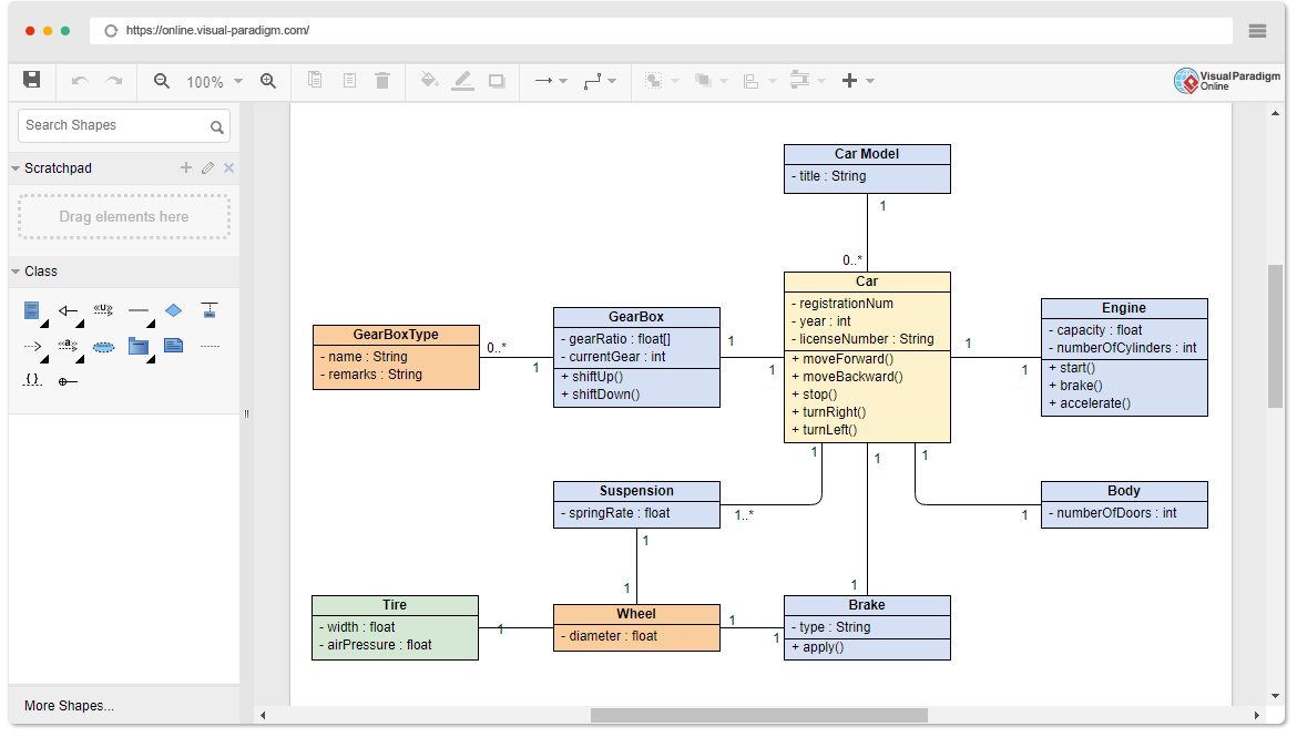
Final Class Diagram
Here is the completed Academic Management System class diagram:
Key Design Decisions and Best Practices
1. Inheritance Strategy
We used generalization to create a hierarchy where Student and Professor inherit from Person. This promotes code reusability and reflects real-world relationships.
2. Association vs. Composition
-
Association: Person to Address (a person can exist without an address)
-
Consider composition for stronger relationships where child objects cannot exist independently
3. Multiplicity Considerations
Carefully defined cardinality to reflect business rules:
-
A student can be supervised by 1 to 5 professors
-
A person can have 0 or more addresses
4. Encapsulation
Used proper visibility modifiers:
-
-for private attributes -
+for public methods
5. Naming Conventions
Maintained consistent naming:
-
CamelCase for class names
-
camelCase for attributes and methods
-
Descriptive, meaningful names
Advanced Features and Next Steps
Code Generation
Visual Paradigm allows you to generate code directly from your class diagrams:
-
Right-click on the diagram
-
Select
Code Engineering>Generate Code -
Choose your target language (Java, C#, Python, etc.)
Reverse Engineering
Import existing code to create class diagrams:
-
Go to
Tools>Code Engineering>Reverse Engineering -
Select your source code files
-
Visual Paradigm automatically generates the class diagram
Model Validation
Use built-in validation tools to ensure diagram consistency and adherence to UML standards.
Team Collaboration
Leverage Visual Paradigm’s collaboration features for team projects:
-
Version control integration
-
Real-time collaboration
-
Model comparison and merging
UML Diagram Examples for Further Learning
Expand your modeling skills with these additional diagram types:

Conclusion
This comprehensive case study has demonstrated the power and practicality of using Visual Paradigm to create professional-grade UML class diagrams for real-world software systems. Through the Academic Management System example, we’ve explored the complete workflow from initial requirements analysis to final diagram documentation, showcasing how visual modeling serves as a critical bridge between conceptual design and implementation.
The step-by-step approach illustrated in this guide emphasizes several key takeaways:
First, class diagrams are indispensable tools for capturing the static structure of software systems. They provide a universal language that facilitates clear communication among developers, stakeholders, and project managers, ensuring everyone has a shared understanding of the system architecture.
Second, Visual Paradigm’s comprehensive feature set transforms the modeling process from a tedious task into an efficient, enjoyable experience. The intuitive interface, drag-and-drop functionality, and powerful automation features enable both novice and experienced developers to create sophisticated models with ease.
Third, the Academic Management System case study demonstrated fundamental object-oriented design principles including inheritance, association, multiplicity, and encapsulation. These principles, when properly applied, result in systems that are maintainable, extensible, and aligned with real-world requirements.
Fourth, the ability to generate code from diagrams and perform reverse engineering creates a seamless development workflow. This bi-directional engineering capability ensures that your models and code remain synchronized throughout the development lifecycle.
Finally, the investment in learning UML modeling and mastering tools like Visual Paradigm pays dividends throughout your software development career. The skills acquired through creating class diagrams translate directly to better system design, reduced development errors, improved team collaboration, and higher-quality software products.
As software systems continue to grow in complexity, the ability to effectively model and visualize architecture becomes increasingly valuable. Whether you’re designing a simple application or architecting an enterprise-level system, Visual Paradigm provides the tools and capabilities you need to succeed. Start applying these techniques to your projects today, and experience the transformative impact of professional-grade visual modeling on your development process.
Ready to elevate your software design skills? Download Visual Paradigm today and begin creating your own professional class diagrams. The combination of theoretical knowledge and practical tool mastery will set you apart as a skilled software architect and developer.
