


Introduction
In the complex world of software architecture, understanding how objects communicate is just as critical as knowing what they do. While Class Diagrams provide a static snapshot of a system’s structure, UML Sequence Diagrams (SD) provide the dynamic narrative. They act as a storyboard for your code, mapping out the chronological flow of messages between participants over time.
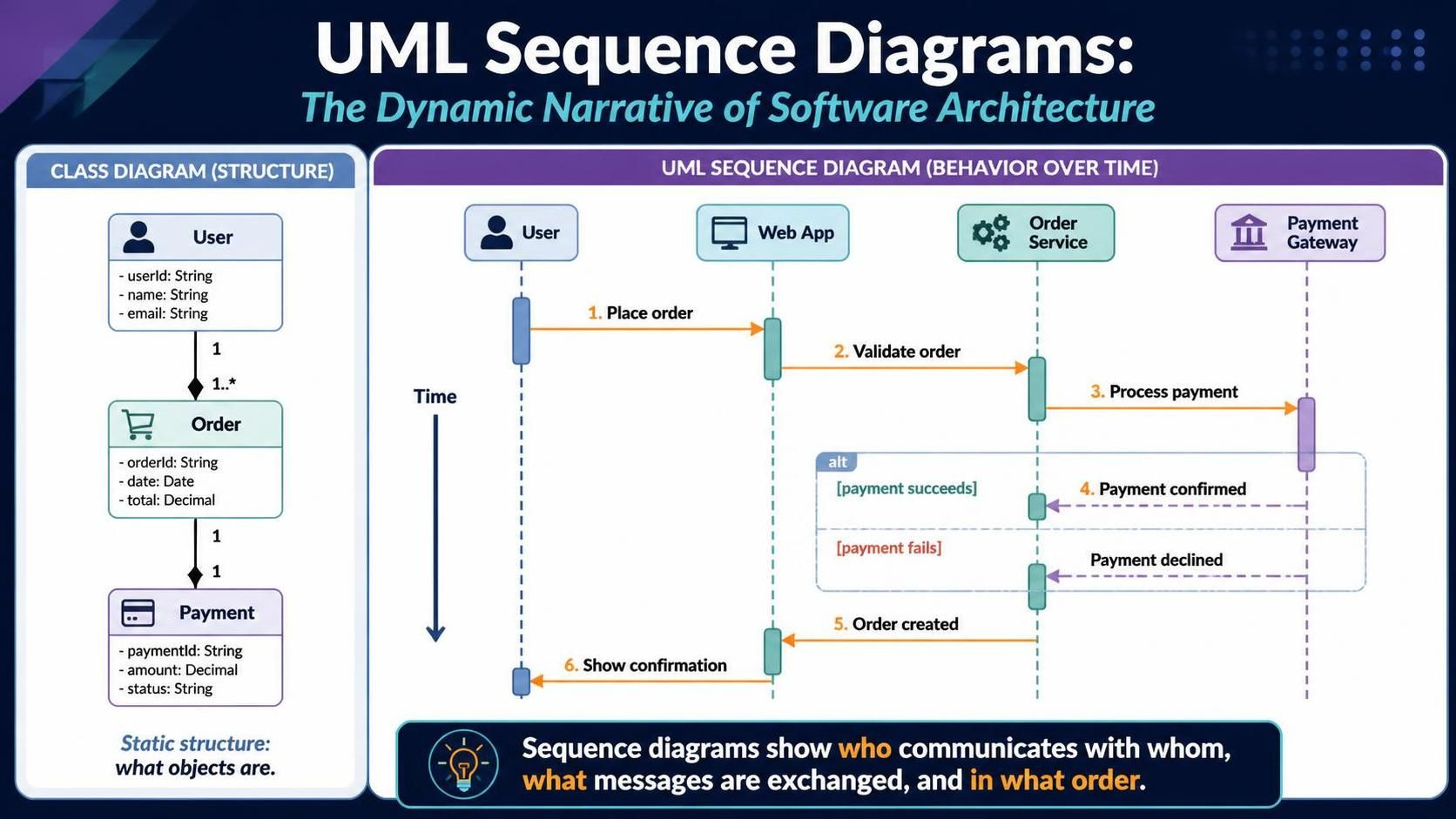
This guide explores the essential building blocks of sequence diagrams—from basic lifelines to advanced combined fragments—and demonstrates how to leverage Visual Paradigm, a leading industry-standard modeling tool, to create precise, professional-grade interaction models that bridge the gap between design and implementation.
1. Core Structural Elements
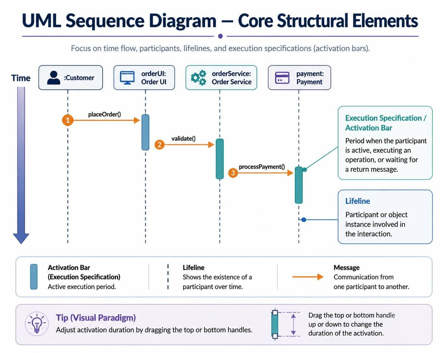
The foundation of any sequence diagram lies in its vertical axis (time) and horizontal axis (participants).
Lifelines
Lifelines represent individual participants or object instances involved in the interaction.
-
Notation: A rectangle containing the name (e.g.,
:Customerorcustomer: Customer) atop a vertical dashed line. -
Purpose: They define the “actors” in the scene. If an object doesn’t have a lifeline, it isn’t part of this specific interaction.
Execution Specifications (Activation Bars)
Also known as activation bars, these are thin vertical rectangles overlaid on a lifeline.
-
Meaning: They indicate the period during which an element is active, executing an operation, or waiting for a return message.
-
Visual Paradigm Tip: In VP, you can drag the top or bottom handles of an execution specification to precisely adjust the duration of an object’s activity.
2. Message Types: The Language of Interaction
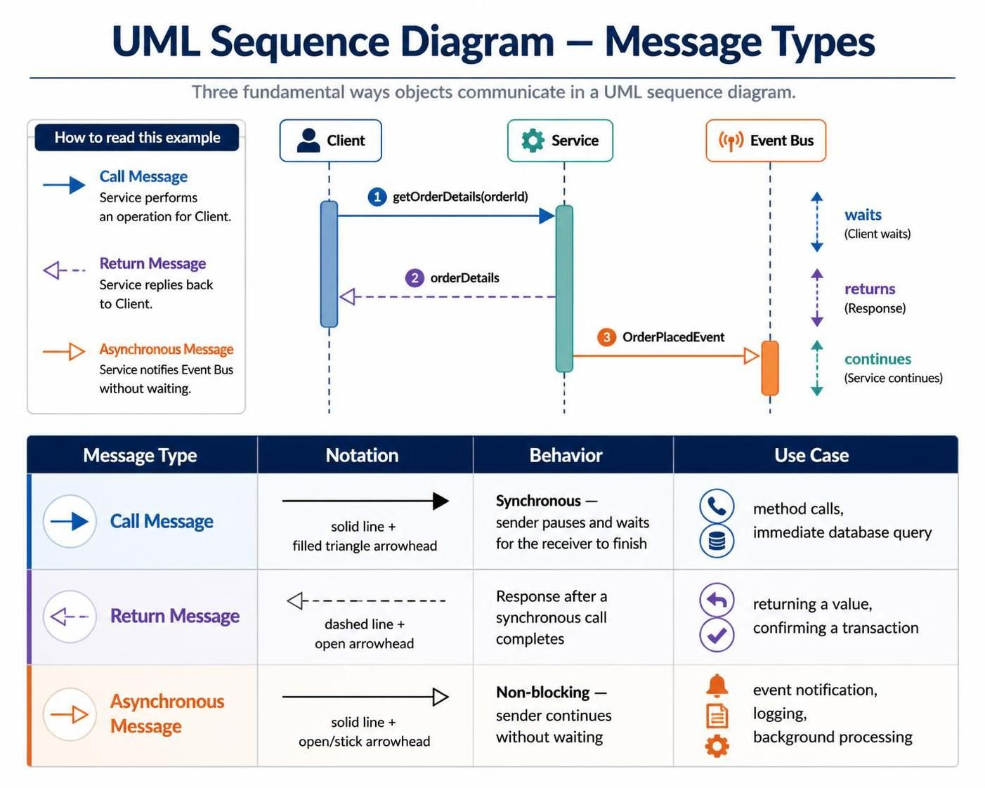
Messages are the horizontal arrows connecting lifelines. The style of the arrow dictates the behavior of the system.
| Message Type | Notation | Behavior | Use Case |
|---|---|---|---|
| Call Message | Solid line, solid triangle arrowhead | Synchronous. The sender pauses and waits for the receiver to complete the task before proceeding. | Method calls, database queries where a result is required immediately. |
| Return Message | Dashed line, open arrowhead | The response flowing back from the receiver to the caller after a synchronous call completes. | Returning a value, confirming a transaction. |
| Asynchronous Message | Solid line, open/stick arrowhead | Non-blocking. The sender fires the message and continues immediately without waiting. | Event notifications, logging, background processing. |
💡 Key Concept: Sync vs. Async
Think of a Call Message like a phone call—you wait on the line for an answer. Think of an Asynchronous Message like sending an email—you hit send and go do something else while waiting for a reply.
3. Combined Fragments & Advanced Notations
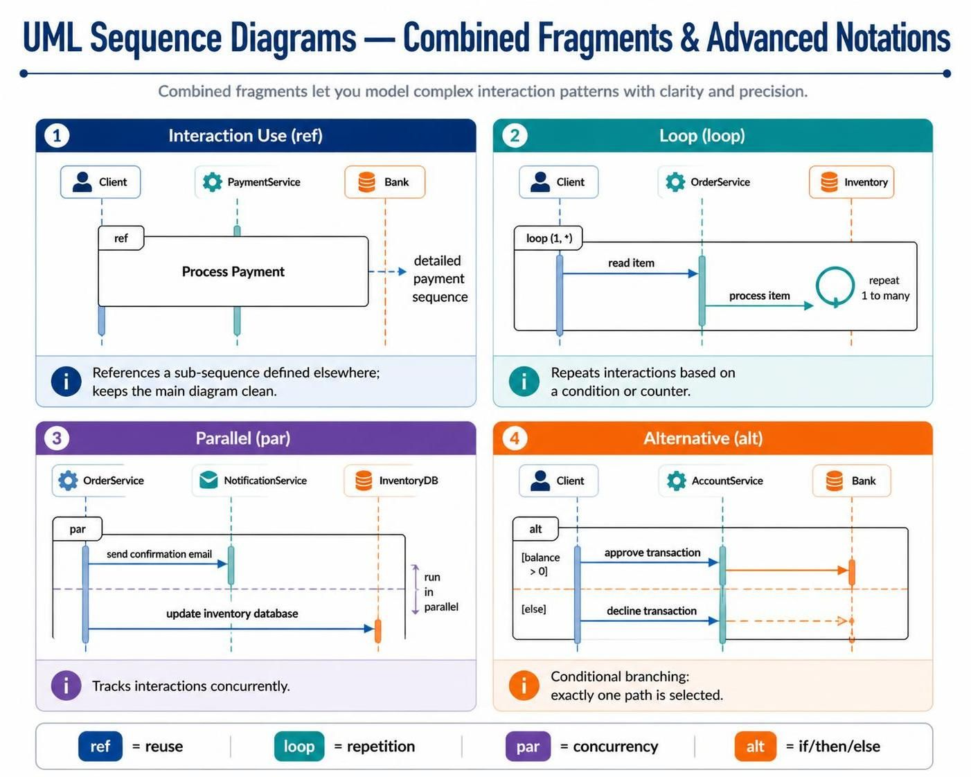
Real-world systems are rarely linear. Combined fragments allow you to model logic, repetition, and concurrency within a single diagram.
Interaction Use (ref)
-
Symbol: A box with
refin the top-left corner. -
Function: References an entire sub-sequence defined in a separate diagram.
-
Why use it? It keeps your main diagram clean. Instead of drawing 50 steps for “Process Payment,” you simply place a
refbox pointing to the detailed payment diagram.
Loop Fragment (loop)
-
Symbol: A box with
loop (min, max)in the top-left corner. -
Function: Repeats the enclosed interactions based on a condition or counter.
-
Example:
loop (1, *)indicates the action repeats at least once, potentially infinitely (like iterating through a list of unknown size).
Parallel Fragment (par)
-
Symbol: A box with
parin the top-left corner, divided by horizontal dashed lines. -
Function: Indicates that the enclosed interaction tracks occur concurrently.
-
Use Case: Sending a confirmation email while simultaneously updating the inventory database.
Alternative Fragment (alt)
-
Symbol: A box with
altin the top-left corner, divided into sections. -
Function: Models conditional branching (If/Then/Else). Only one path is executed based on a guard condition (e.g.,
[balance > 0]). -
Note: Unlike
opt(option),altrequires that one of the paths must be chosen.
4. Tooling Spotlight: Visual Paradigm
Visual Paradigm (VP) is widely regarded as one of the most robust tools for UML modeling due to its strict adherence to UML standards and powerful automation features.
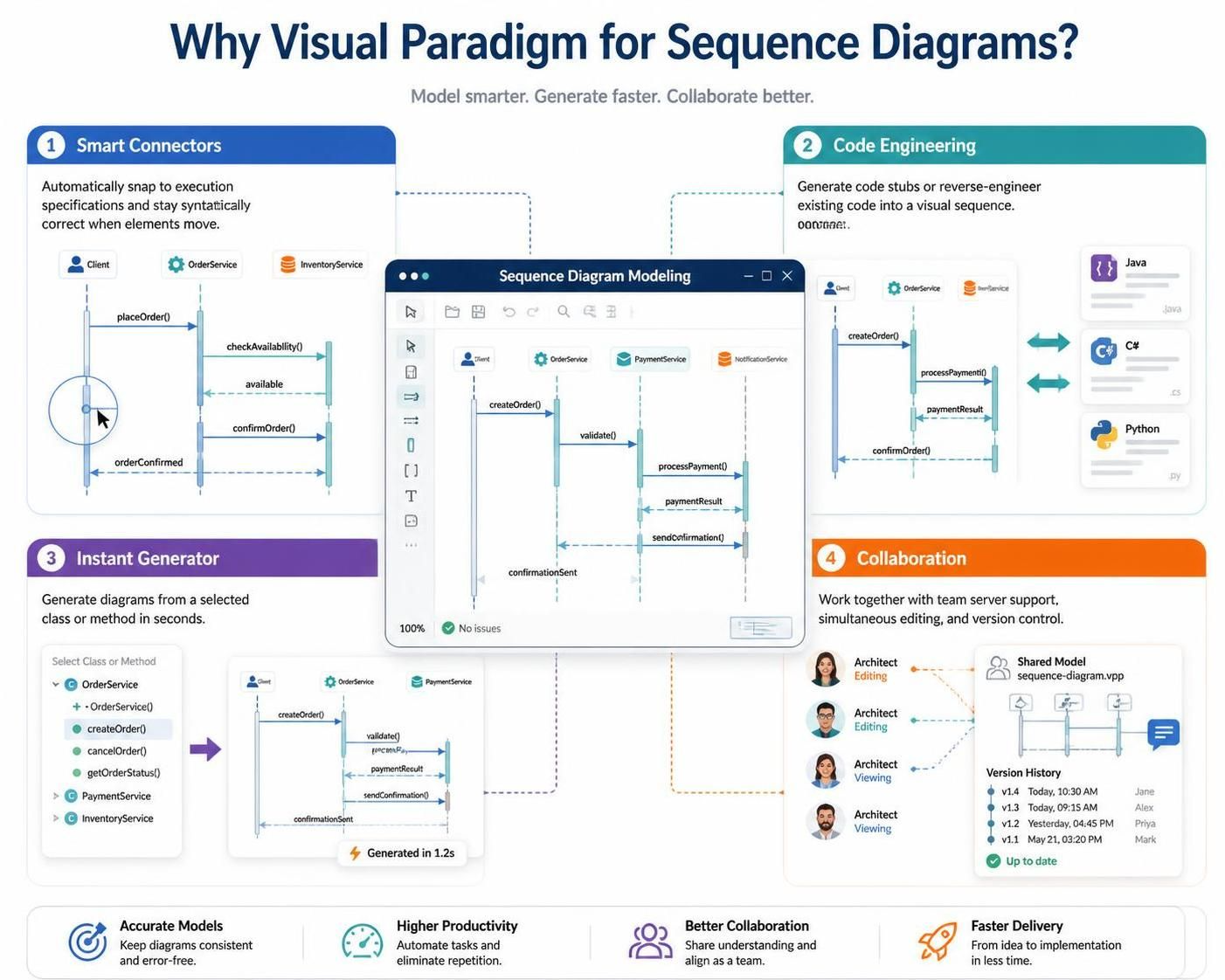
Why Visual Paradigm for Sequence Diagrams?
-
Smart Connectors: VP’s message connectors automatically snap to execution specifications, ensuring your diagram remains syntactically correct even when you rearrange elements.
-
Code Engineering: VP supports round-trip engineering. You can generate Java/C#/Python stubs directly from your sequence diagram, or reverse-engineer existing code into a visual sequence.
-
Instant Generator: For large systems, VP can automatically generate a sequence diagram from a selected class or method, saving hours of manual drafting.
-
Collaboration: Built-in team server capabilities allow multiple architects to work on the same model simultaneously with version control.
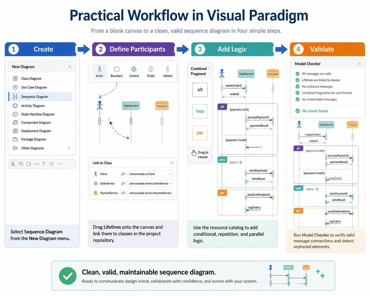
Practical Workflow in VP
-
Create: Select “Sequence Diagram” from the New Diagram menu.
-
Define Participants: Drag “Lifeline” shapes onto the canvas; VP will prompt you to link them to existing classes in your project repository.
-
Add Logic: Use the “Combined Fragment” resource catalog to drag-and-drop
alt,loop, orparframes. -
Validate: Run the “Model Checker” to ensure all messages connect validly and no orphaned elements exist.
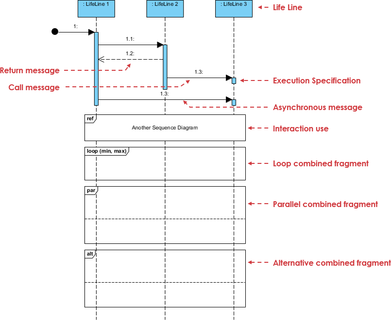
Online Bookstore Order Checkout Scenario
-
LifeLine 1: The Checkout UI / Client Application (initiates the process)
-
LifeLine 2: The Order Service (handles business logic, cart processing, and validations)
-
LifeLine 3: The Payment Gateway (processes secure financial transactions)
Scenario Workflow Breakdown
-
Initiation & Call: The user submits their order through the Checkout UI, which triggers an initial call message to the Order Service. The Order Service activates its execution specification to process the request.
-
Loop Validation: The system enters a loop fragment (
loop (min, max)) where the Order Service validates every individual item in the user’s shopping cart against the inventory database to check stock availability. -
Parallel Processing: Once items are validated, the system triggers a parallel fragment (
par) to simultaneously reserve the inventory items and notify the warehouse fulfillment service without blocking the main thread. -
Alternative Branching: Next, an alternative fragment (
alt) handles the payment outcome:-
Success Path: If the Payment Gateway successfully charges the user’s card (via an asynchronous message and call), an order confirmation is generated.
-
Failure Path: If the payment fails or times out, the system rolls back the inventory reservation and prompts the user to update their payment details.
-
-
Modular Reference: Throughout the checkout flow, the system utilizes an interaction use (
ref) to handle user authentication and session verification by referencing a separate login sequence diagram. -
Return Message: Finally, the Order Service sends a return message back to the Checkout UI with the final transaction status, terminating the active execution specification.
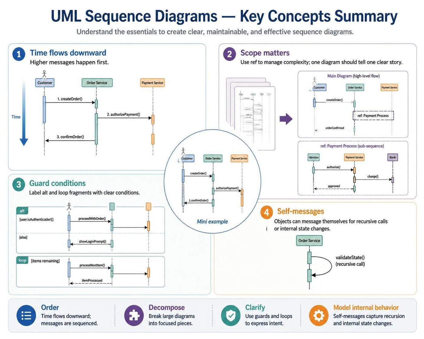
Key Concepts Summary
-
Time flows downward: The vertical position of a message determines its order. Higher messages happen first.
-
Scope matters: Use
refto manage complexity. A sequence diagram should tell one clear story; if it spans three pages, break it up. -
Guard Conditions: Always label your
altandloopfragments with clear conditions (e.g.,[user.isAuthenticated()]) to avoid ambiguity. -
Self-Messages: Don’t forget that objects can send messages to themselves (recursive calls or internal state changes), represented by an arrow looping back to the same lifeline.
Conclusion
UML Sequence Diagrams are more than just documentation; they are a communication tool that aligns developers, testers, and stakeholders on the expected behavior of a system. By mastering the distinction between synchronous and asynchronous messaging, and effectively utilizing combined fragments for complex logic, you can model even the most intricate architectures with clarity.
When paired with a powerful tool like Visual Paradigm, these diagrams transition from static drawings to living artifacts that drive code generation and validate system integrity. Whether you are designing a microservices API or documenting a legacy monolith, the sequence diagram remains the definitive map of your system’s runtime behavior.

 English
 Arabic
 Chinese (Simplified)
 Dutch
Dutch French
 German
 Italian
 Japanese
 Korean
 Portuguese
 Russian
 Spanish