


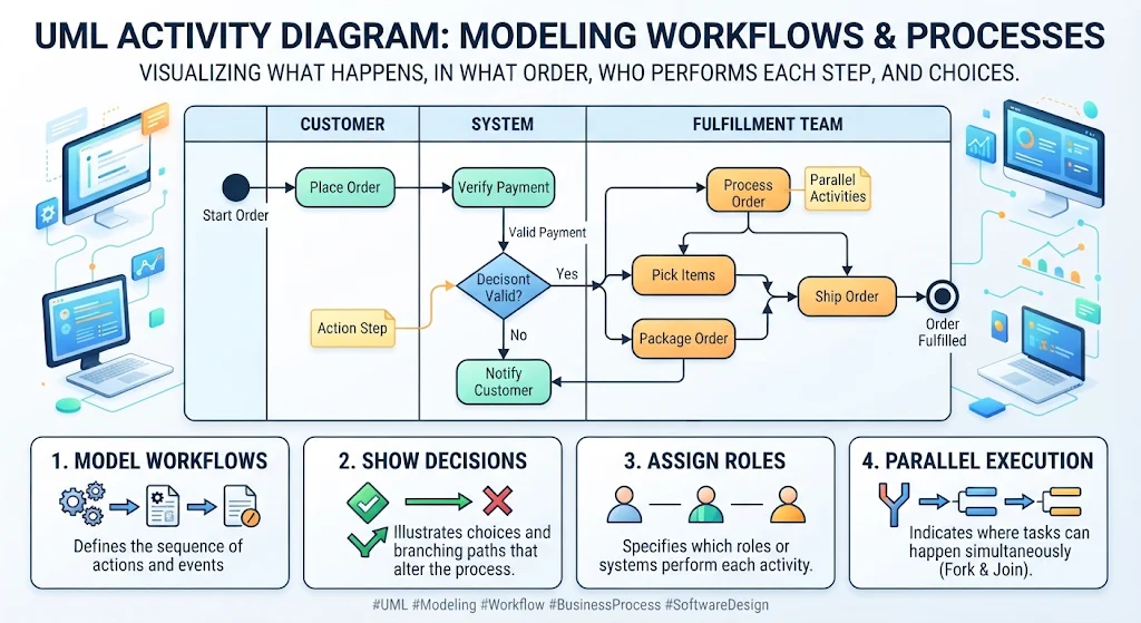
A UML activity diagram models the flow of work: what happens, in what order, what choices alter the path, which roles perform each step, and where work can happen in parallel. It can describe a business process or the behavior inside a software system. In a use-case-driven project, it is especially useful for turning a use case’s written scenario into a visual, reviewable workflow
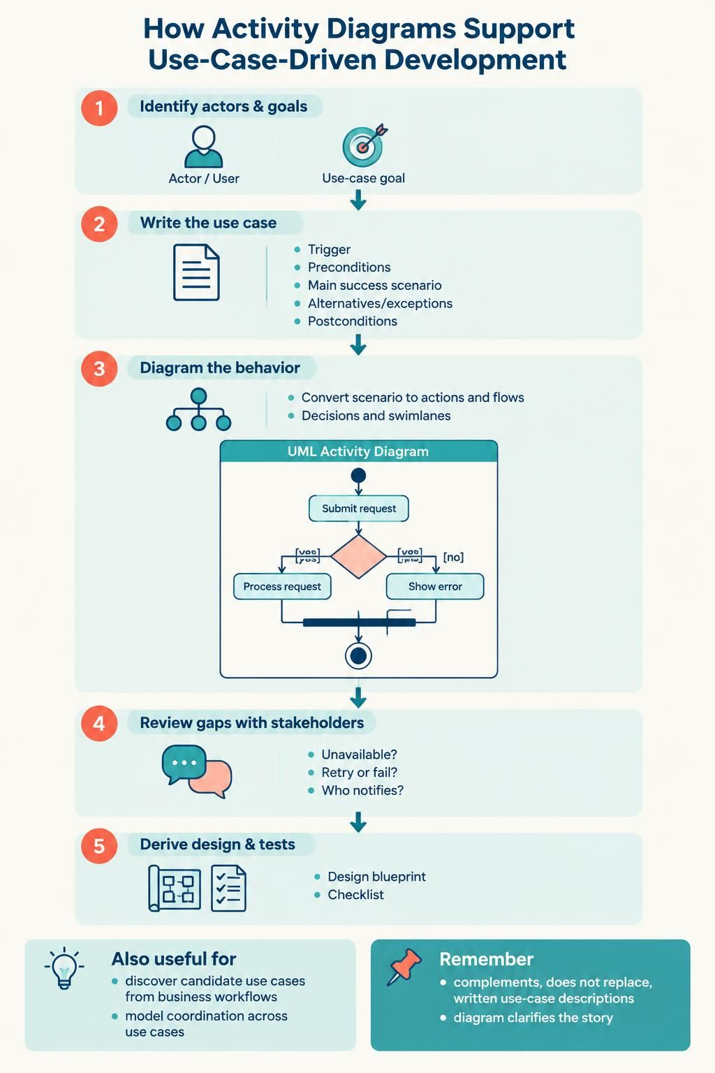
How activity diagrams support use-case-driven development
Use cases establish what goal a user or external system wants to achieve. An activity diagram helps elaborate how the scenario proceeds: the main success path, alternatives, errors, and responsibilities.
A practical sequence is:
-
Identify actors and goals. Use a use-case diagram or stakeholder discussion to identify who interacts with the system and what each actor wants to accomplish.
-
Write the use case. Define its goal, trigger, preconditions, main success scenario, alternatives or exceptions, and postconditions.
-
Diagram the behavior. Convert the scenario into actions and flows. Add decision points for alternatives and swimlanes when ownership or system boundaries matter.
-
Review gaps with stakeholders. The visual flow often exposes unanswered questions: What if inventory is unavailable? Does a timeout lead to a retry or a failure? Who is responsible for notifying the customer?
-
Derive design and tests. Use the clarified paths to inform sequence or interaction design, implementation tasks, and test scenarios.
Activity diagrams can also help discover candidate use cases by showing a larger business workflow, and they can model how several use cases coordinate. They complement—not replace—use-case descriptions: the diagram should clarify the story, not become the only place where requirements live.
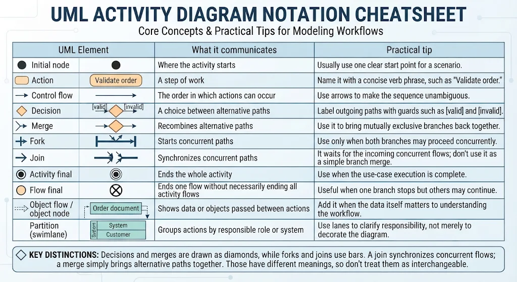
Core concepts
| UML element | What it communicates | Practical tip |
|---|---|---|
| Initial node | Where the activity starts | Usually use one clear start point for a scenario. |
| Action | A step of work | Name it with a concise verb phrase, such as “Validate order.” |
| Control flow | The order in which actions can occur | Use arrows to make the sequence unambiguous. |
| Decision | A choice between alternative paths | Label outgoing paths with guards such as [valid] and [invalid]. |
| Merge | Recombines alternative paths | Use it to bring mutually exclusive branches back together. |
| Fork | Starts concurrent paths | Use only when both branches may proceed concurrently. |
| Join | Synchronizes concurrent paths | It waits for the incoming concurrent flows; don’t use it as a simple branch merge. |
| Activity final | Ends the whole activity | Use when the use-case execution is complete. |
| Flow final | Ends one flow without necessarily ending all activity flows | Useful when one branch stops but others may continue. |
| Object flow / object node | Shows data or objects passed between actions | Add it when the data itself matters to understanding the workflow. |
| Partition (swimlane) | Groups actions by responsible role or system | Use lanes to clarify responsibility, not merely to decorate the diagram. |
Decisions and merges are drawn as diamonds, while forks and joins use bars. A join synchronizes concurrent flows; a merge simply brings alternative paths together. Those have different meanings, so don’t treat them as interchangeable.
Example: Place an order
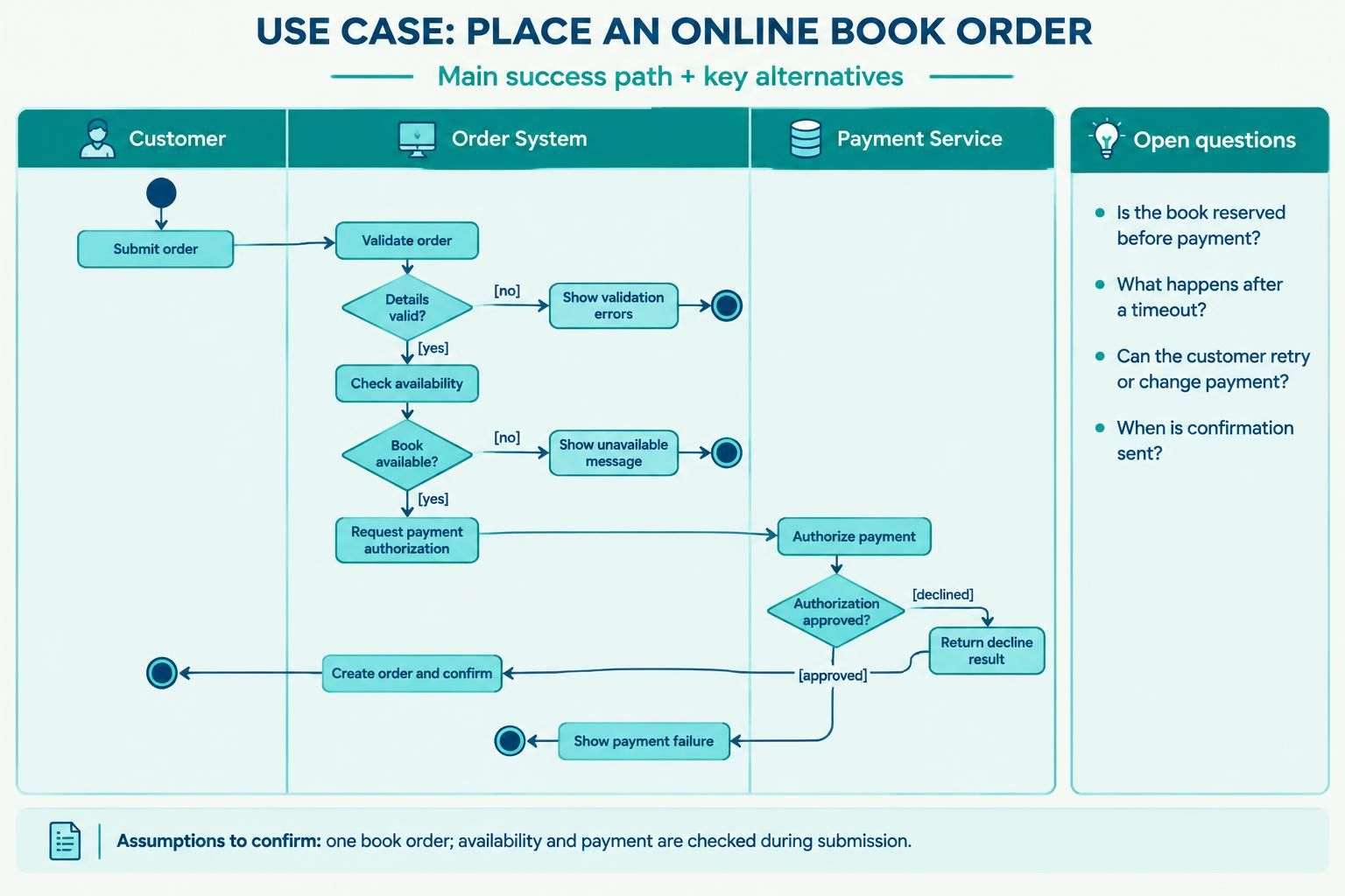
This example models a simplified use case. The customer submits an order; the system checks inventory, processes payment, and handles success or failure. It uses lanes to show responsibility and guards to name decision outcomes.
Render with VPasCode Tool for the PlantUML Activity Diagram: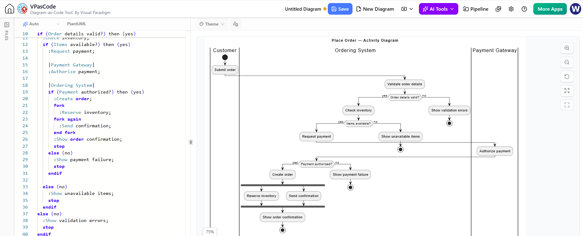
@startuml
title Place Order — Activity Diagram

|Customer|
start
:Submit order;

|Ordering System|
:Validate order details;
if (Order details valid?) then (yes)
  :Check inventory;
  if (Items available?) then (yes)
    :Request payment;

    |Payment Gateway|
    :Authorize payment;

    |Ordering System|
    if (Payment authorized?) then (yes)
      :Create order;
      fork
        :Reserve inventory;
      fork again
        :Send confirmation;
      end fork
      :Show order confirmation;
      stop
    else (no)
      :Show payment failure;
      stop
    endif

  else (no)
    :Show unavailable items;
    stop
  endif
else (no)
  :Show validation errors;
  stop
endif
@enduml
The fork indicates that inventory reservation and confirmation can proceed concurrently in this simplified example. If the business rules require one to finish before the other begins, replace the fork with a sequential flow. Treat the code as a starting point: confirm whether the real system sends confirmation before or after reservation, and define what happens if either operation fails.
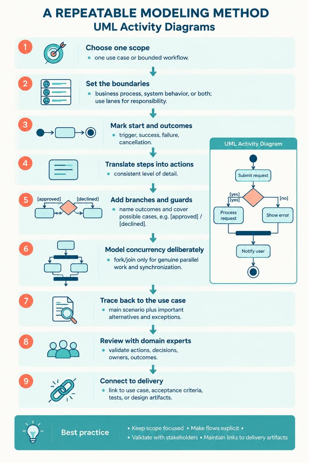
A repeatable modeling method
-
Choose one scope. Model one use case or one clearly bounded workflow at a time—not the entire product.
-
Set the boundaries. Decide whether the diagram describes a user’s business process, the system’s internal behavior, or both. Use lanes to make responsibility clear.
-
Mark the start and outcomes. Identify the trigger, successful completion, and meaningful failure or cancellation outcomes.
-
Translate steps into actions. Keep each action at a consistent level of detail. A step such as “Process order” may be too broad if the purpose is to clarify validation, payment, and fulfillment.
-
Add branches and guards. Every meaningful condition should have named outcomes. Check that the guards cover the possible cases—for example,
[approved]and[declined], rather than only one branch. -
Model concurrency deliberately. Use a fork and join only when work truly runs in parallel and the synchronization point matters.
-
Trace the diagram back to the use case. Confirm that the main scenario and each important alternative or exception are represented.
-
Review with the people who know the work. Ask whether every action, decision, owner, and outcome reflects the actual process.
-
Connect it to delivery. Link the diagram to its use case, acceptance criteria, tests, or design artifacts so it remains useful beyond analysis.
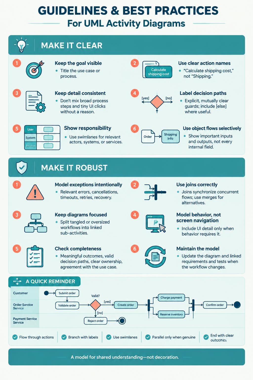
Guidelines and best practices
-
Keep the goal visible. Give the diagram a title that identifies the use case or business process.
-
Use clear action names. Prefer “Calculate shipping cost” over vague labels such as “Shipping.”
-
Keep the level of detail consistent. Don’t mix high-level steps such as “Fulfill order” with low-level clicks such as “Press the blue button” unless that detail is specifically needed.
-
Label decision paths. Make conditions explicit and mutually clear; use an
[else]or equivalent default path when appropriate. -
Show responsibility when it matters. A lane for the system and one for each relevant actor or external service can make handoffs easier to review.
-
Use object flows selectively. Show inputs and outputs when data is important to the requirement; don’t add every field or internal variable.
-
Make exceptional behavior intentional. Include relevant errors, cancellations, timeouts, retries, and recovery paths. Avoid trying to enumerate every technical failure in a stakeholder-level diagram.
-
Avoid ambiguous joins. A join waits for all required incoming flows. If branches are alternatives, use a merge instead.
-
Avoid tangled lines and oversized diagrams. Split a complex workflow into linked sub-activities or separate diagrams, with each diagram focused on a reviewable question.
-
Don’t confuse process flow with screen navigation. Model user-interface details only when they are part of the behavior being specified.
-
Check completeness and consistency. Each start should lead to a meaningful outcome; decisions should have valid paths; actions should have understandable ownership; and the diagram should agree with the written use case.
-
Treat the diagram as a model, not decoration. If the workflow changes, update the diagram and its linked requirements and tests.
Activity diagrams are useful for showing workflow, decision paths, and possible parallel work; swimlanes help group actions by responsible party.
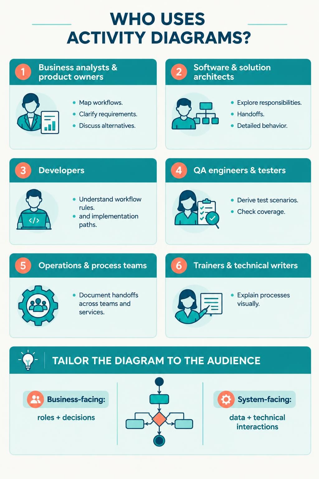
Who uses activity diagrams?
-
Business analysts and product owners map business workflows, clarify requirements, and discuss alternatives with stakeholders.
-
Software and solution architects explore system responsibilities, handoffs, and behavior that needs more detailed design.
-
Developers use the model to understand workflow rules and identify paths that need implementation.
-
QA engineers and testers use the main and alternative flows to derive test scenarios and check coverage.
-
Operations and process teams document handoffs and responsibilities across teams or services.
-
Trainers and technical writers explain a process to readers who need a visual overview.
A diagram can serve multiple audiences, but it should be tailored to the question they need answered. A business-facing model may emphasize roles and decisions; a system-facing model may include data and technical interactions.
Tooling: Visual Paradigm UML, VPasCode, and AI assistance
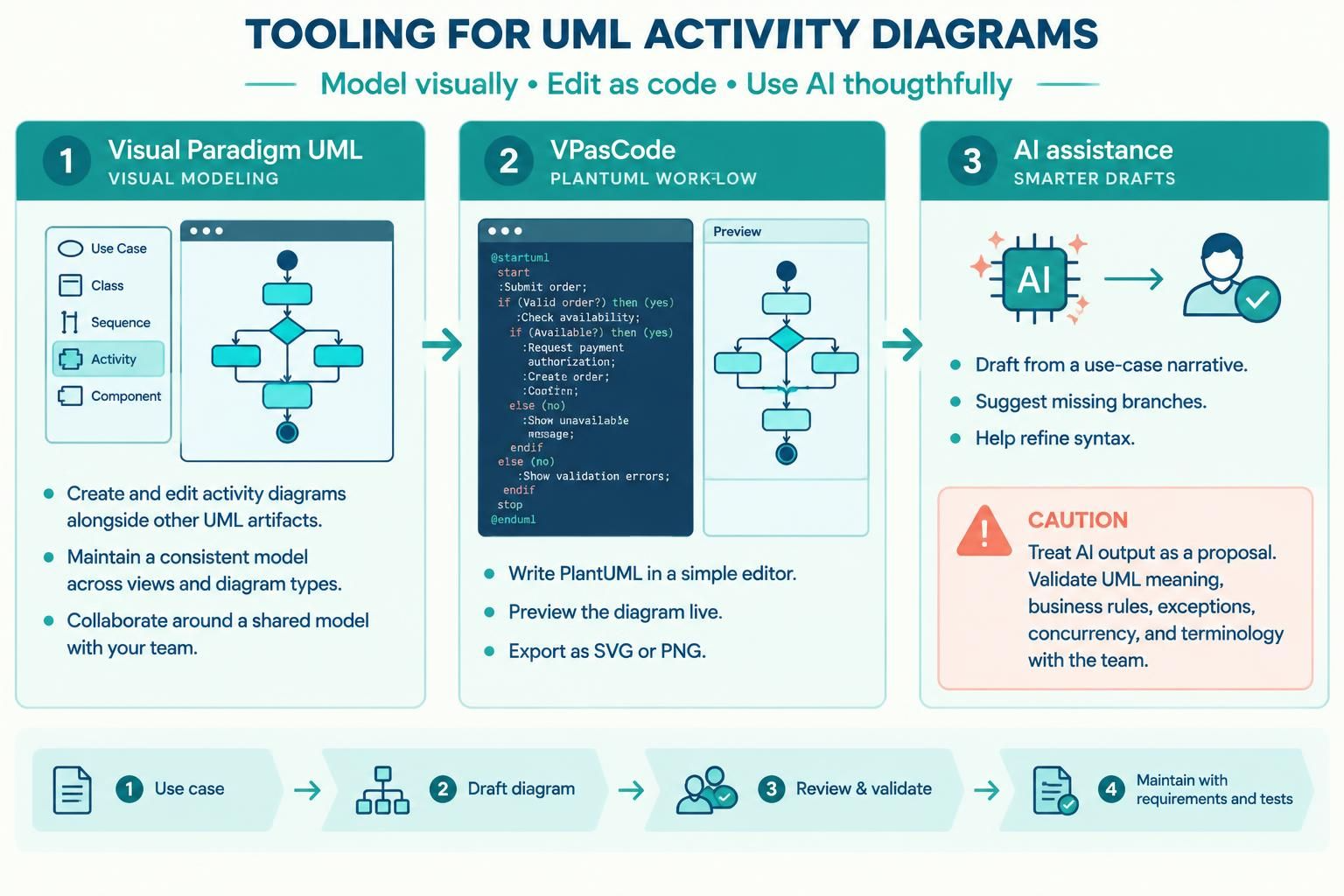
A useful workflow can combine a visual UML modeler, diagram-as-code editing, and AI as a drafting or review aid.
-
Visual Paradigm UML: Use a visual modeling environment when you want to draw and maintain activity diagrams alongside other UML artifacts, or to collaborate through a model-based workflow. Visual Paradigm’s activity-diagram guide describes use cases such as modeling workflows within use cases, pre- and postconditions, and business processes.
-
VPasCode: Use it to write and preview PlantUML text directly. Visual Paradigm describes VPasCode as a browser-based diagram-as-code editor that supports PlantUML activity diagrams, live rendering, and exports such as SVG and PNG. It also describes AI diagram generation and editing capabilities; some advanced features are identified as paid options.
-
AI-assisted modeling: Use AI to draft a diagram from a use-case narrative, suggest missing branches, or refine PlantUML syntax. Visual Paradigm describes AI-assisted use-case work and a workflow for moving AI-generated diagrams into VPasCode for further editing. Treat AI output as a proposal: validate UML meaning, business rules, exceptions, concurrency, and terminology with the team before adopting it.
A practical toolchain is: write and review the use case → generate or sketch a first activity diagram → refine it in Visual Paradigm or VPasCode → review the rendered diagram with stakeholders → save the source and link it to requirements and tests. PlantUML is especially convenient when you want diagrams in text files that can be reviewed and versioned; a visual modeler may be preferable when the wider project is managed as a connected UML model.
AI prompt you can adapt:
Create a UML activity diagram in PlantUML for the following use case. Include a main success path, important alternative and failure paths, and swimlanes for the responsible actor, system, and external services. Use explicit decision guards. Do not assume missing business rules; list them separately as open questions. Keep the diagram at a consistent level of detail. Use forks and joins only for genuine concurrent work. Here is the use case: [paste the use case]
The most valuable outcome is not a polished diagram by itself. It is a shared, testable understanding of how the use case behaves—including who does what, what can go wrong, and what counts as completion.

 English
 Arabic
 Chinese (Simplified)
 Dutch
 French
 German
 Italian
 Japanese
 Korean
 Portuguese
 Russian
 Spanish