


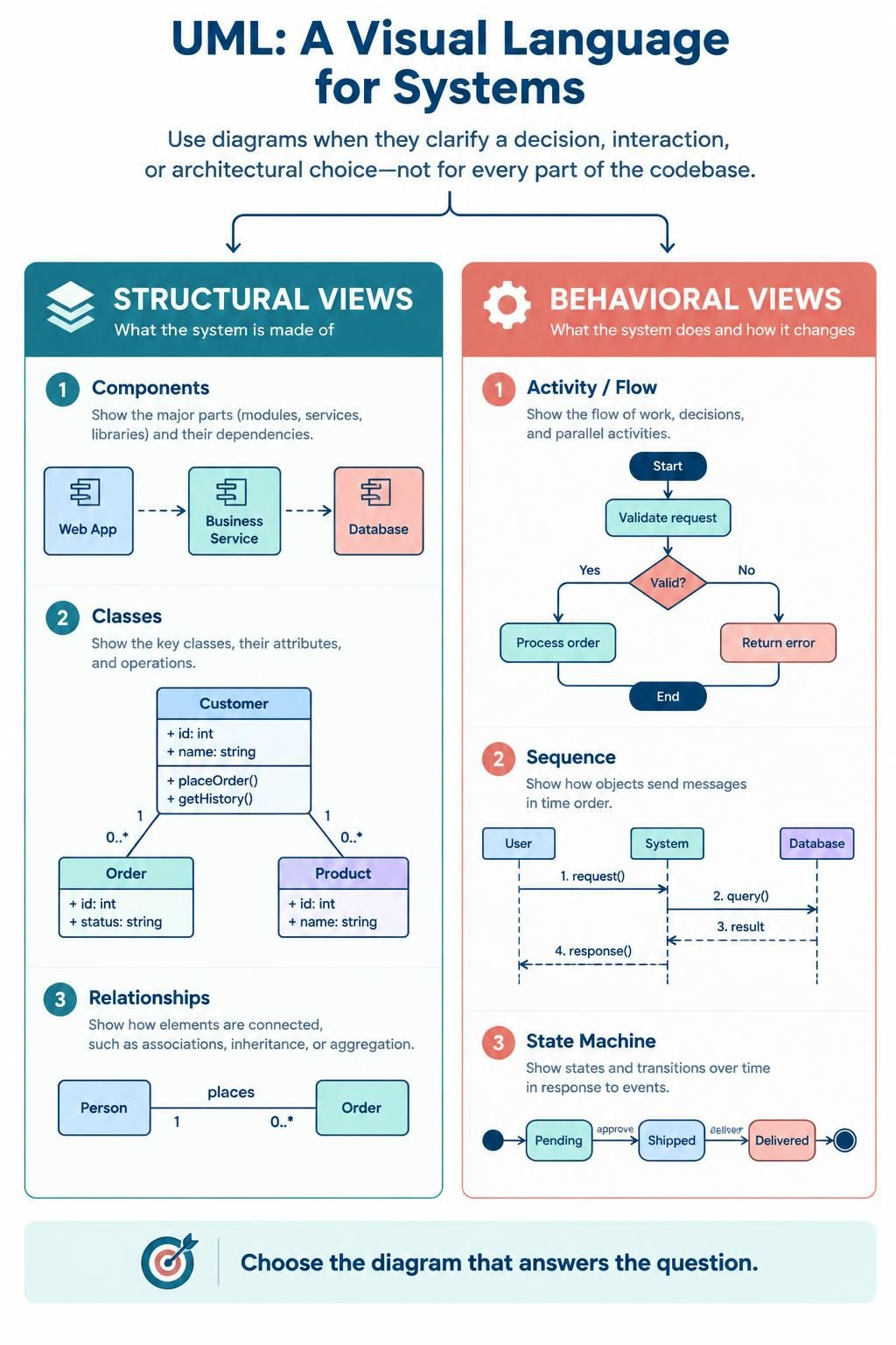
UML (Unified Modeling Language) is a shared visual notation for describing a system’s structure and behavior. Use it to make a specific decision, explain a complex interaction, or record an architectural choice—not to produce a diagram for every part of the codebase. UML’s diagrams are broadly divided into structural views (what the system is made of) and behavioral views (what it does and how it changes).
Choose a diagram by the question you need to answer
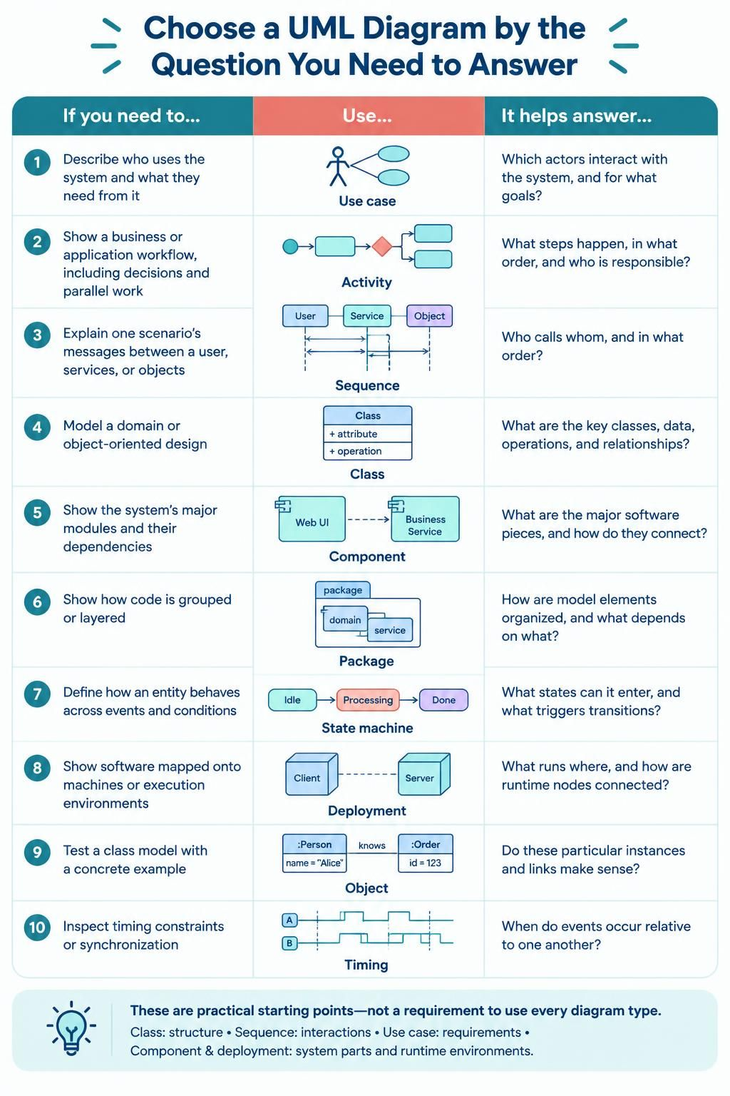
| If you need to… | Use… | It helps answer… |
|---|---|---|
| Describe who uses the system and what they need from it | Use case | Which actors interact with the system, and for what goals? |
| Show a business or application workflow, including decisions and parallel work | Activity | What steps happen, in what order, and who is responsible? |
| Explain one scenario’s messages between a user, services, or objects | Sequence | Who calls whom, and in what order? |
| Model a domain or object-oriented design | Class | What are the key classes, data, operations, and relationships? |
| Show the system’s major modules and their dependencies | Component | What are the major software pieces, and how do they connect? |
| Show how code is grouped or layered | Package | How are model elements organized, and what depends on what? |
| Define how an entity behaves across events and conditions | State machine | What states can it enter, and what triggers transitions? |
| Show software mapped onto machines or execution environments | Deployment | What runs where, and how are runtime nodes connected? |
| Test a class model with a concrete example | Object | Do these particular instances and links make sense? |
| Inspect timing constraints or synchronization | Timing | When do events occur relative to one another? |
These are practical starting points, not a requirement to use every diagram type. Class diagrams are useful for object-oriented structures; sequence diagrams clarify interactions; and use case diagrams help frame system requirements. Component and deployment diagrams are especially useful when a system has multiple parts or runtime environments.
Use UML throughout the lifecycle
1. Discovery and requirements
Start by clarifying the system boundary, users, and outcomes. A use case diagram can summarize actors and their goals. Use activity diagrams when a process has important decisions, exceptions, or handoffs between roles.
Keep requirements in plain language as well as diagrams. A use case diagram is an overview, not a detailed requirements specification: document acceptance criteria, rules, and error cases separately.
2. Architecture and design
Use a component diagram to agree on major services, modules, and dependencies. Add a deployment diagram when infrastructure, network boundaries, or placement of runtime components matters. For a larger codebase, package diagrams can make layering and dependency direction easier to discuss.
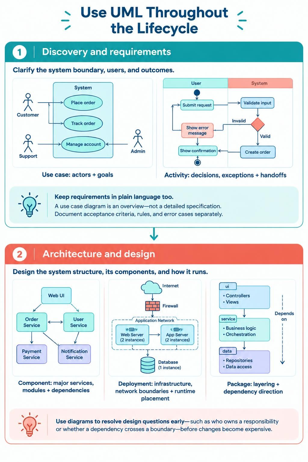
At this stage, diagrams should help resolve questions—such as which component owns a responsibility or whether a dependency crosses a boundary—before those choices become expensive to change.
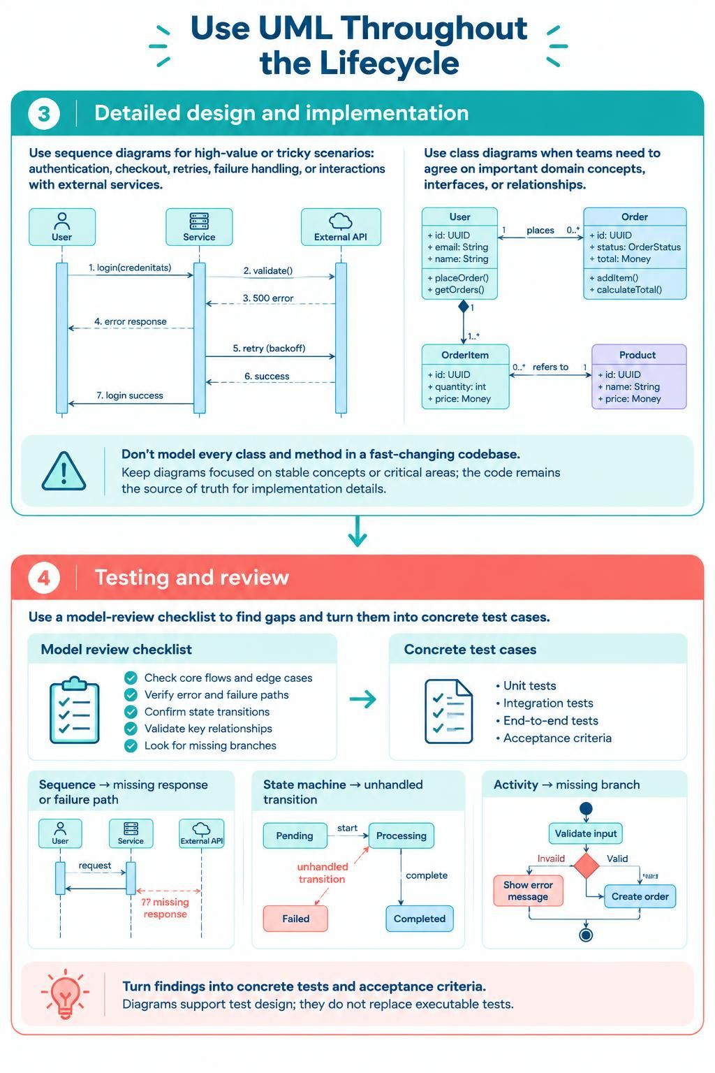
3. Detailed design and implementation
Use sequence diagrams for high-value or tricky scenarios: authentication, checkout, retries, failure handling, or interactions with external services. Use class diagrams when teams need to agree on important domain concepts, interfaces, or relationships.
Avoid trying to model every class and method in a fast-changing codebase. Keep detailed diagrams focused on stable concepts or critical areas, and let the code remain the source of truth for implementation details.
4. Testing and review
Compare the models with expected behavior. A sequence diagram can help expose a missing response or failure path; a state machine can reveal an unhandled transition; an activity diagram can surface a missing branch. Turn those cases into concrete tests and acceptance criteria—the diagram supports test design but does not replace executable tests.
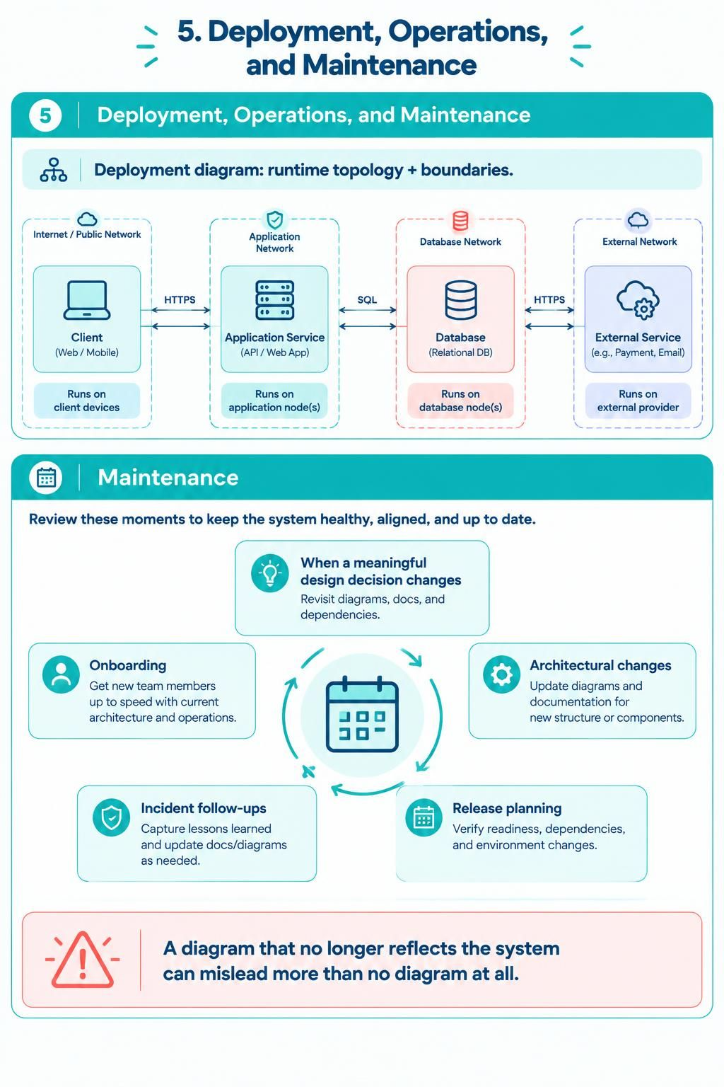
5. Deployment, operations, and maintenance
Use deployment diagrams to communicate runtime topology and boundaries. Update diagrams when a meaningful design decision changes, and review them during architectural changes, incident follow-ups, onboarding, and release planning. A diagram that no longer reflects the system can mislead more than no diagram at all.
A lightweight workflow for each diagram
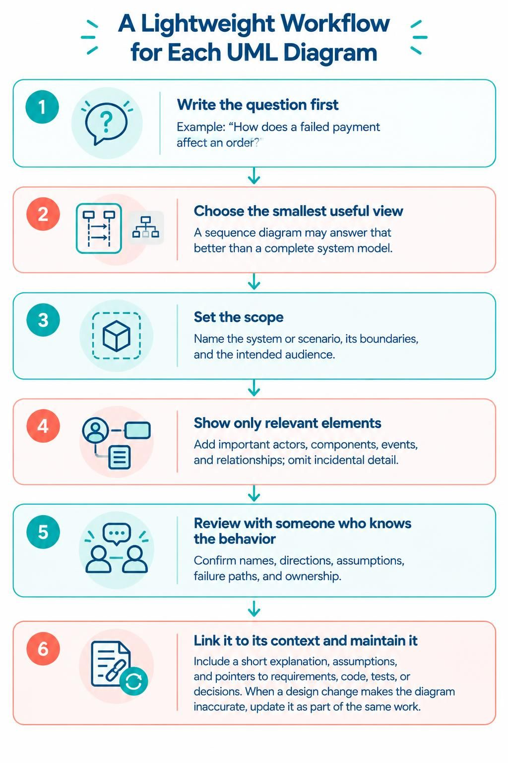
-
Write the question first. For example: “How does a failed payment affect an order?”
-
Choose the smallest useful view. A sequence diagram may answer that better than a complete system model.
-
Set the scope. Name the system or scenario, its boundaries, and the intended audience.
-
Show only relevant elements. Add important actors, components, events, and relationships; omit incidental detail.
-
Review with someone who knows the behavior. Confirm names, directions, assumptions, failure paths, and ownership.
-
Link it to its context. Include a short explanation, assumptions, and pointers to requirements, code, tests, or decisions.
-
Maintain it with the change. When a design change makes the diagram inaccurate, update it as part of the same work.
Applying the Visual Paradigm toolchain
A useful way to organize the tools is: generate a draft → refine the model → publish the explanation.
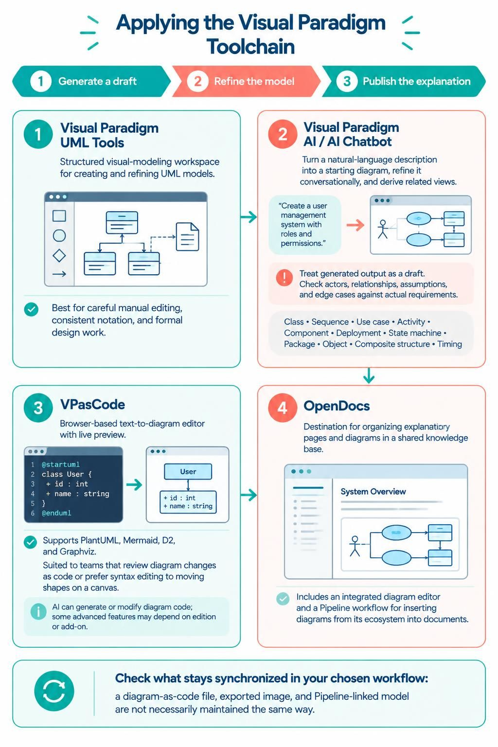
-
Visual Paradigm UML tools are the better fit when you need a structured visual-modeling workspace for creating and refining UML models. Use this route for diagrams that need careful manual editing, consistent notation, or more formal design work.
-
Visual Paradigm AI / AI Chatbot can turn a natural-language description into a starting diagram, support conversational refinement, and help derive related views. Treat generated output as a draft: check that its actors, relationships, assumptions, and edge cases match the actual requirements. Visual Paradigm lists UML types including class, sequence, use case, activity, component, deployment, state machine, package, object, composite structure, and timing diagrams.
-
VPasCode is a browser-based text-to-diagram editor for formats including PlantUML, Mermaid, D2, and Graphviz, with live preview. It suits teams that want diagram definitions in text, can review changes as code, or prefer editing syntax over moving shapes on a canvas. Its AI features can generate or modify diagram code; some advanced features may depend on the edition or add-on.
-
OpenDocs is the documentation destination: use it to organize explanatory pages and diagrams in a shared knowledge base. Visual Paradigm describes both an integrated diagram editor and a Pipeline workflow for inserting diagrams from its ecosystem into documents. The exact behavior depends on the path used: a diagram-as-code file, an exported image, and a Pipeline-linked model are not necessarily maintained the same way. Confirm what stays synchronized in your chosen workflow.
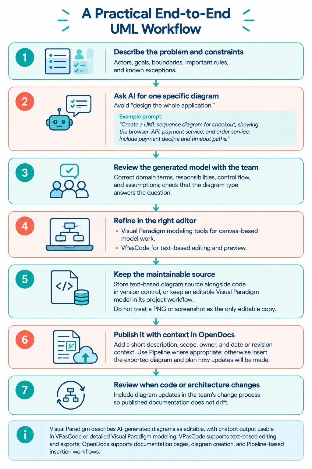
A practical end-to-end workflow is:
-
Describe the problem and constraints—actors, goals, boundaries, important rules, and known exceptions.
-
Ask the AI for one specific diagram rather than a broad “design the whole application” request. For example: “Create a UML sequence diagram for checkout, showing the browser, API, payment service, and order service. Include payment decline and timeout paths.”
-
Review the generated model with the team. Correct domain terms, responsibilities, control flow, and assumptions; then check that the selected diagram type actually answers the question.
-
Refine in the right editor. Use Visual Paradigm’s modeling tools for canvas-based model work, or move a text-based diagram into VPasCode for code editing and preview.
-
Keep the maintainable source. If the diagram is text-based, store its source alongside the code in version control. If it is a Visual Paradigm model, keep the editable model in its project workflow. Avoid treating a PNG or screenshot as the only editable copy.
-
Publish it with context in OpenDocs. Add a short description, scope, owner, and date or revision context. Use the Pipeline where appropriate; otherwise, insert the exported diagram and plan how updates will be made.
-
Review diagrams when relevant code or architecture changes. Include diagram updates in the team’s change process so the published documentation does not drift.
Visual Paradigm describes AI-generated diagrams as editable and supports passing chatbot output into VPasCode or into more detailed Visual Paradigm modeling; VPasCode also supports text-based editing and exports. OpenDocs supports documentation pages, diagram creation, and Pipeline-based insertion workflows.
Good habits—and common mistakes
-
One diagram, one purpose. Split a crowded system map into focused views, such as a component overview and a separate checkout sequence.
-
Name relationships clearly. A labeled arrow is easier to interpret than a line whose meaning is implied.
-
Show exceptions when they matter. For important flows, include failures, retries, timeouts, and alternate paths.
-
Keep abstraction consistent. Don’t mix business-level roles and low-level implementation details in one view unless that contrast is intentional.
-
Don’t confuse UML types. An activity diagram shows workflow; a sequence diagram shows message order; a state machine shows an entity’s state transitions.
-
Avoid diagram-first design without validation. A plausible-looking model can still invent requirements or omit constraints. Confirm it with product, engineering, and operations as relevant.
-
Don’t over-document. Model the parts where shared understanding, risk reduction, or future maintenance justify the effort.
-
Make ownership clear. A named maintainer and a review trigger help keep important diagrams current.
A sensible starter set
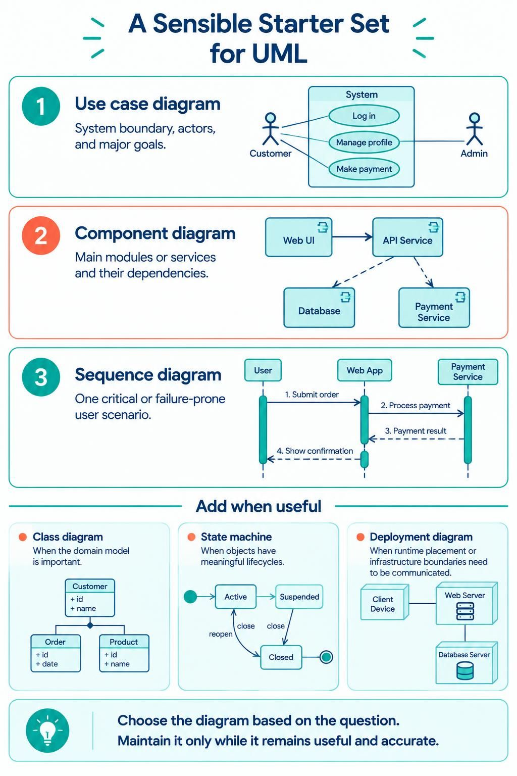
For many software projects, begin with just three views:
-
Use case diagram — system boundary, actors, and major goals.
-
Component diagram — main modules or services and their dependencies.
-
Sequence diagram — one critical or failure-prone user scenario.
Add a class diagram if the domain model is important, a state machine if objects have meaningful lifecycles, and a deployment diagram if runtime placement or infrastructure boundaries need to be communicated. The guiding rule is simple: choose the diagram based on the question, and maintain it only while it remains useful and accurate.

 English
 Arabic
 Chinese (Simplified)
 Dutch
 French
 German
 Italian
 Japanese
 Korean
 Portuguese
 Russian
 Spanish