


Introduction
In today’s complex software development landscape, modeling dynamic system behavior is more critical than ever. State Machine Diagrams—formally known as UML State Machine Diagrams—provide a powerful visual language for representing how objects respond to events across different states throughout their lifecycle. Whether you’re designing an e-commerce order processing system, an IoT device controller, or a banking transaction workflow, understanding state-dependent behavior is fundamental to building robust, maintainable systems.
This comprehensive case study explores the theory, notation, and practical application of State Machine Diagrams, while demonstrating how modern AI-powered tools like Visual Paradigm are revolutionizing the way teams design, refine, and deploy behavioral models. By combining foundational UML principles with conversational AI assistance, developers and architects can now transform abstract requirements into precise, executable state logic faster and with greater confidence than ever before.

What is a State Machine Diagram?
The behavior of an entity is not only a direct consequence of its inputs, but it also depends on its preceding state. The past history of an entity can best be modeled by a finite state machine diagram or traditionally called automata. UML State Machine Diagrams (or sometimes referred to as state diagram, state machine or state chart) show the different states of an entity. State machine diagrams can also show how an entity responds to various events by changing from one state to another. State machine diagram is a UML diagram used to model the dynamic nature of a system.
Why State Machine Diagrams?
State machine diagram typically are used to describe state-dependent behavior for an object. An object responds differently to the same event depending on what state it is in. State machine diagrams are usually applied to objects but can be applied to any element that has behavior to other entities such as: actors, use cases, methods, subsystems systems and etc. and they are typically used in conjunction with interaction diagrams (usually sequence diagrams).
For example:
Consider you have $100,000 in a bank account. The behavior of the withdraw function would be: balance := balance – withdrawAmount; provided that the balance after the withdrawal is not less than $0; this is true regardless of how many times you have withdrawn money from the bank. In such situations, the withdrawals do not affect the abstraction of the attribute values, and hence the gross behavior of the object remains unchanged.
However, if the account balance would become negative after a withdrawal, the behavior of the withdraw function would be quite different. This is because the state of the bank account is changed from positive to negative; in technical jargon, a transition from the positive state to the negative state is fired.
The abstraction of the attribute value is a property of the system, rather than a globally applicable rule. For example, if the bank changes the business rule to allow the bank balance to be overdrawn by 2000 dollars, the state of the bank account will be redefined with condition that the balance after withdrawal must not be less than $2000 in deficit.
Note That:
-
A state machine diagram describes all events (and states and transitions for a single object)
-
A sequence diagram describes the events for a single interaction across all objects involved
Basic Concepts of State Machine Diagram
What is a State?
Rumbaugh defines that:
“A state is an abstraction of the attribute values and links of an object. Sets of values are grouped together into a state according to properties that affect the gross behavior of the object.”
State Notation
Characteristics of State Machine Notations
There are several characteristics of states in general, regardless of their types:
-
A state occupies an interval of time.
-
A state is often associated with an abstraction of attribute values of an entity satisfying some condition(s).
-
An entity changes its state not only as a direct consequence of the current input, but it is also dependent on some past history of its inputs.
State
A state is a constraint or a situation in the life cycle of an object, in which a constraint holds, the object executes an activity or waits for an event.
A state machine diagram is a graph consisting of:
-
States (simple states or composite states)
-
State transitions connecting the states
Example:
Characteristics of State
-
State represent the conditions of objects at certain points in time.
-
Objects (or Systems) can be viewed as moving from state to state
-
A point in the lifecycle of a model element that satisfies some condition, where some particular action is being performed or where some event is waited
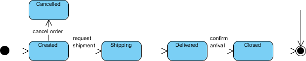
Initial and Final States
-
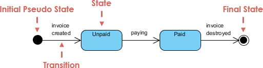
The initial state of a state machine diagram, known as an initial pseudo-state, is indicated with a solid circle. A transition from this state will show the first real state
-
The final state of a state machine diagram is shown as concentric circles. An open loop state machine represents an object that may terminate before the system terminates, while a closed loop state machine diagram does not have a final state; if it is the case, then the object lives until the entire system terminates.
Example:
Events
An event signature is described as Event-name (comma-separated-parameter-list). Events appear in the internal transition compartment of a state or on a transition between states. An event may be one of four types:
-
Signal event – corresponding to the arrival of an asynchronous message or signal
-
Call event – corresponding to the arrival of a procedural call to an operation
-
Time event – a time event occurs after a specified time has elapsed
-
Change event – a change event occurs whenever a specified condition is met
Characteristics of Events
-
Represents incidents that cause objects to transition from one state to another.
-
Internal or External Events trigger some activity that changes the state of the system and of some of its parts
-
Events pass information, which is elaborated by Objects operations. Objects realize Events
-
Design involves examining events in a state machine diagram and considering how those events will be supported by system objects
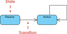
Transition
Transition lines depict the movement from one state to another. Each transition line is labeled with the event that causes the transition.
-
Viewing a system as a set of states and transitions between states is very useful for describing complex behaviors
-
Understanding state transitions is part of system analysis and design
-
A Transition is the movement from one state to another state
-
Transitions between states occur as follows:
-
An element is in a source state
-
An event occurs
-
An action is performed
-
The element enters a target state
-
-
Multiple transitions occur either when different events result in a state terminating or when there are guard conditions on the transitions
-
A transition without an event and action is known as automatic transitions
Actions
Action is an executable atomic computation, which includes operation calls, the creation or destruction of another object, or the sending of a signal to an object. An action is associated with transitions and during which an action is not interruptible – e.g., entry, exit
Activity
Activity is associated with states, which is a non-atomic or ongoing computation. Activity may run to completion or continue indefinitely. An Activity will be terminated by an event that causes a transition from the state in which the activity is defined
Characteristics of Action and Activities
-
States can trigger actions
-
States can have a second compartment that contains actions or activities performed while an entity is in a given state
-
An action is an atomic execution and therefore completes without interruption
-
Five triggers for actions: On Entry, Do, On Event, On Exit, and Include
-
An activity captures complex behavior that may run for a long duration – An activity may be interrupted by events, in which case it does not complete occur when an object arrives in a state.
Simple State Machine Diagram Notation
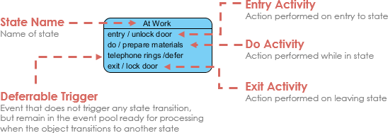
Entry and Exit Actions
Entry and Exit actions specified in the state. It must be true for every entry / exit occurrence. If not, then you must use actions on the individual transition arcs
-
Entry Action executed on entry into state with the notation: Entry / action
-
Exit Action executed on exit from state with the notation: Exit / action
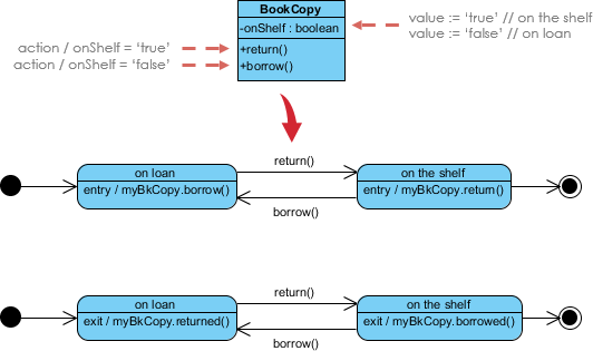
Example – Entry / Exit Action (Check Book Status)
This example illustrates a state machine diagram derived from a Class – “BookCopy”:
Note:
-
This state machine diagram shows the state of an object myBkCopy from a BookCopy class
-
Entry action : any action that is marked as linked to the entry action is executed whenever the given state is entered via a transition
-
Exit action : any action that is marked as linked to the exit action is executed whenever the state is left via a transition
Advanced State Modeling: Substates, History, and Concurrency
Substates
A simple state is one which has no substructure. A state which has substates (nested states) is called a composite state. Substates may be nested to any level. A nested state machine may have at most one initial state and one final state. Substates are used to simplify complex flat state machines by showing that some states are only possible within a particular context (the enclosing state).
Substate Example – Heater
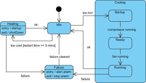
State Machine Diagrams are often used for deriving testing cases, here is a list of possible test ideas:
-
Idle state receives Too Hot event
-
Idle state receives Too Cool event
-
Cooling/Startup state receives Compressor Running event
-
Cooling/Ready state receives Fan Running event
-
Cooling/Running state receives OK event
-
Cooling/Running state receives Failure event
-
Failure state receives Failure Cleared event
-
Heating state receives OK event
-
Heating state receives Failure event
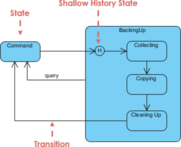
History States
Unless otherwise specified, when a transition enters a composite state, the action of the nested state machine starts over again at the initial state (unless the transition targets a substate directly). History states allow the state machine to re-enter the last substate that was active prior to leaving the composite state. An example of history state usage is presented in the figure below.
Concurrent State
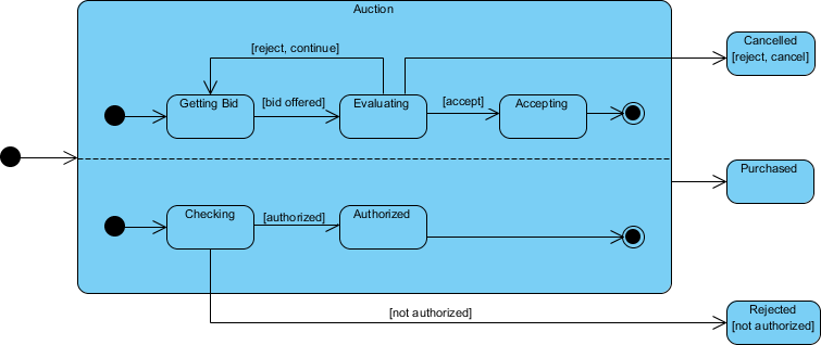
As mentioned above, states in state machine diagrams can be nested. Related states can be grouped together into a single composite state. Nesting states inside others is necessary when an activity involves concurrent sub-activities. The following state machine diagram models an auction with two concurrent substates: processing the bid and authorizing the payment limit.
Concurrent State Machine Diagram Example – Auction Process
In this example, the state machine first entering the Auction requires a fork at the start into two separate start threads. Each substate has an exit state to mark the end of the thread. Unless there is an abnormal exit (Canceled or Rejected), the exit from the composite state occurs when both substates have exited.
How to Draw a State Machine Diagram in UML?
A state machine Diagram (or start diagram, also called state chart of state transition diagram) is a behavior which specifies the sequence of states an entity (or object) visits during its lifetime in response to events, together with its responses to those events.
State diagram at a glance
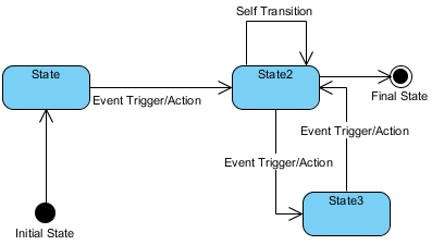
Key concepts
State
A state is a condition during the life of an object during which it satisfies some condition, performs some activity, or waits for some external event
Event
An event is the specification of a significant occurrence. For a state machine, an event is the occurrence of a stimulus that can trigger a state transition.
Transition
A transition is a relationship between two states indicating that an object in the first state will, when a specified set of events and conditions are satisfied, perform certain actions and enter the second state.
Action
An action is an executable, atomic (with reference to the state machine) computation. Actions may include operations, the creation or destruction of other objects, or the sending of signals to other objects (events).
Creating a State Machine Diagram
-
Select Diagram > New from the tool bar.
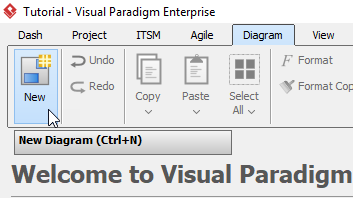
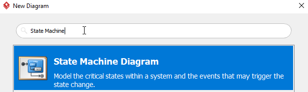
-
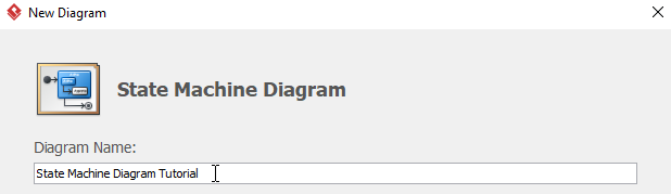
In the New Diagram window, select State Machine Diagram, then click Next. you can use the search bar above to filter results.
-
Name the diagram, then click OK. In this tutorial, we will name the diagram State Machine Diagram Tutorial.
-
You will now see an empty diagram with an initial pseudo state.
-
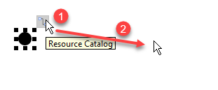
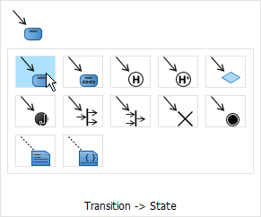
To Create a new state, click the initial state, then drag the resource button to the desire position and release. When release the button, choose Transition -> State from the popup window. Once the state is created, you may change the name of the state.
-
Repeat step 5 for more states.
-
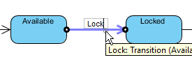
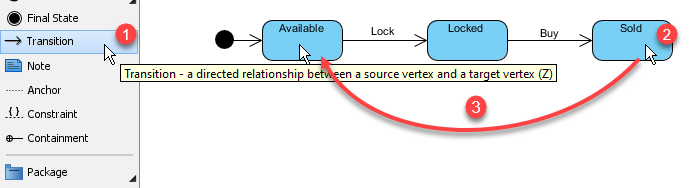
No you may see the transitions are not named. You can name a transition by double clicking the transition. This example will name the transition between Available and Locked to Lock.
-
Once all the states are created, you may want to set up more transitions. You can do this by selecting Transition, click and hold on the starting state (Sold in this example), then drag to the destination state (Available in this example) and release. Do not forget to name the transition.
-
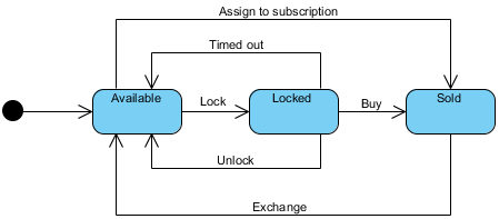
You are expected to see a diagram like this when you finish your diagram:
Case Study: AI-Powered State Machine Design for an E-Commerce Order Lifecycle
Scenario Overview
An online retail platform needs to model the complete lifecycle of a customer order—from placement through fulfillment, shipping, and potential returns. The system must handle multiple concurrent processes (payment authorization, inventory allocation, shipping coordination) while maintaining clear state transitions for auditability and customer communication.
Traditional Approach Challenges
Manually designing this state machine would require:
-
Mapping 15+ distinct order states (Pending, Payment Authorized, Inventory Reserved, Shipped, Delivered, Returned, Cancelled, etc.)
-
Defining guard conditions for each transition (e.g., “Payment Authorized AND Inventory Available → Order Confirmed”)
-
Managing concurrent substates for payment processing and warehouse fulfillment
-
Ensuring all edge cases are covered (payment failures, stock shortages, shipping delays)
AI-Assisted Solution with Visual Paradigm
Step 1: Natural Language Prompt
Using Visual Paradigm’s AI Chatbot, the product team enters:
“Generate a state machine diagram for an e-commerce order system. Include states for order placement, payment processing, inventory check, fulfillment, shipping, delivery, and returns. Add guard conditions for payment failure and out-of-stock scenarios. Support concurrent processing for payment and inventory checks.”
Step 2: AI-Generated Diagram
The AI instantly produces a syntactically correct UML state machine with:
-
Initial pseudo-state and final delivery/return states
-
Composite states for “Payment Processing” and “Fulfillment” with nested substates
-
Guard conditions like
[payment successful]and[inventory available] -
Entry/exit actions for logging and notification triggers
Step 3: Conversational Refinement
The team iteratively refines the model via chat:
-
“Add a timeout transition from Payment Pending to Cancelled after 15 minutes”
-
“Create a history state for the Fulfillment composite to resume interrupted processing”
-
“Color all error transitions red for visibility”
Step 4: Validation & Gap Analysis
The AI engine analyzes the diagram and flags:
-
A missing transition for “Partial Shipment” scenarios
-
Recommendation to add a “Customer Notification” action on state entry for Shipped/Delivered states
-
Suggestion to model refund processing as a concurrent region alongside return logistics
Step 5: Documentation & Code Generation
With the model finalized, the team leverages Visual Paradigm to:
-
Auto-generate technical documentation describing each state’s business rules
-
Export Java skeleton code with enum-based state definitions and transition methods
-
Push the diagram to the desktop client for version control integration with the development team
Outcome
-
70% reduction in initial modeling time compared to manual UML tooling
-
Clear, auditable state logic shared across product, engineering, and QA teams
-
Automated test case generation derived directly from state transitions
-
Seamless handoff from design to implementation with generated code scaffolds
Master Complex Object Lifecycles with AI
State machines are essential for modeling event-driven behavior, but nested substates and concurrent regions can be challenging to design manually. Visual Paradigm’s AI tools simplify this by transforming your behavioral logic into precise UML State Charts—complete with triggers, guards, and entry/exit actions.
AI-Enabled Platforms
-
VP Desktop: Use the integrated AI assistant to generate and refine state-dependent logic directly within the UML modeler.
-
AI Chatbot: Describe your object’s states and transitions to the AI Chat for instant, editable diagram generation.
Smart Behavioral Design
🔄 Transition Discovery: AI automatically identifies states and transitions from your system requirements.
🛡️ Time Saving: Generate diagram in one click, few seconds.
Learn More about AI State Diagramming Full AI Ecosystem
Core Traditional UML Statechart Features
Once your diagram is initialized by the AI, Visual Paradigm exposes robust, industry-standard modeling features to expand your architecture:
| Feature Category | Technical Capabilities |
|---|---|
| Hierarchical Modeling | Full support for composite states (sub-states) and parallel orthogonal regions to model complex, simultaneous system activities. |
| Transition Properties | Native data entries for specifying formal triggers/events, conditional guards, and executable behavioral actions ($Event [Guard] / Action$). |
| State Lifecycles | Discrete structural mapping for Entry, Do, and Exit behaviors belonging to individual states. |
| Pseudo-states | Precision workflow routing utilizing choice blocks, junctions, history states (shallow/deep), forks, and joins. |
Documentation & Code Pipelines
Visual Paradigm ensures that your conversational AI mockups are fully integrated with professional development workflows:
-
Seamless Tool Promotion: AI-sketched diagrams created online can be instantly pushed directly into the Visual Paradigm Desktop App to leverage advanced configuration, team version control, and system compliance check pipelines.
-
On-Demand Technical Documentation: You can instruct the AI tool to draft contextual project summaries, software requirements specifications (SRS), or architecture design proposals built right from the states and paths present in your visual chart.
-
Automated State Code Generation: The software converts the visual transitions, choices, and state lifecycles directly into backend source code frameworks, supporting object-oriented structures in Java, C++, and Python.
Conclusion
State Machine Diagrams remain an indispensable tool for modeling the dynamic, event-driven behavior of complex systems. By capturing how objects transition between states in response to events, teams can design more predictable, maintainable, and testable software architectures. The integration of AI-powered capabilities into modern UML tools like Visual Paradigm represents a paradigm shift—transforming state modeling from a manual, error-prone exercise into an interactive, conversational design process.
Whether you’re a seasoned systems architect or a developer new to behavioral modeling, leveraging AI assistance allows you to focus on the logic and business rules that matter most, while the tool handles syntactic precision, gap analysis, and documentation overhead. As systems grow increasingly asynchronous and distributed, the ability to clearly visualize and validate state transitions becomes not just advantageous, but essential. By embracing AI-enhanced state machine modeling, teams can accelerate design cycles, reduce implementation defects, and build systems that gracefully handle the complexity of real-world user interactions.
References
- Mastering UML State Machine Diagrams with Visual Paradigm AI: A comprehensive guide exploring how AI integration enhances traditional UML statechart modeling workflows for enterprise systems.
- Mastering UML State Machine Diagrams with AI-Powered Visual Modeling: An in-depth article on leveraging conversational AI to accelerate behavioral design and validation in complex software projects.
- Mastering State Diagrams with Visual Paradigm AI: A Guide for Automated Toll Systems: Practical case study demonstrating AI-assisted state machine design for real-time embedded systems.
- Comprehensive Guide to UML State Machine Diagrams with Visual Paradigm and AI: End-to-end tutorial covering foundational concepts, advanced features, and AI-powered automation for statechart development.
- Visual Paradigm AI Chatbot Features: Official documentation detailing conversational AI capabilities for diagram generation, refinement, and knowledge querying within the Visual Paradigm ecosystem.
- AI Diagram Generator Now Supports 13 Diagram Types: Release announcement highlighting expanded AI support for UML and non-UML diagram types, including state machines.
- OpenDocs Update: AI State Diagram Generator: Product update detailing new AI-powered state machine generation features in Visual Paradigm’s web-based OpenDocs platform.
- Beginner’s Guide to State Machine Diagrams: Introductory tutorial for newcomers to UML statecharts, covering core notation, semantics, and modeling best practices.
- How Visual Paradigm’s AI Chatbot Revolutionizes Diagram Creation for Teams: Analysis of collaborative benefits and productivity gains from AI-assisted visual modeling in team environments.
- Guide to Powered UML Diagram Generation: Interactive guide for using Visual Paradigm’s AI chat interface to generate and refine UML diagrams through natural language prompts.
- Guide to Powered UML Diagram Generation (Vietnamese): Localized version of the AI diagram generation guide, supporting Vietnamese-speaking users in leveraging conversational modeling tools.
- AI Component Diagram Generator Update: Technical update on AI enhancements for component and deployment diagrams, complementing state machine modeling capabilities.
- Comprehensive Review: Visual Paradigm’s AI Diagram Generation Features: Independent third-party evaluation of AI-powered diagramming tools, with focus on usability, accuracy, and integration capabilities.
- Visual Paradigm AI State Machine Tutorial Video: Step-by-step video demonstration of creating and refining UML state machine diagrams using Visual Paradigm’s AI assistant.
